
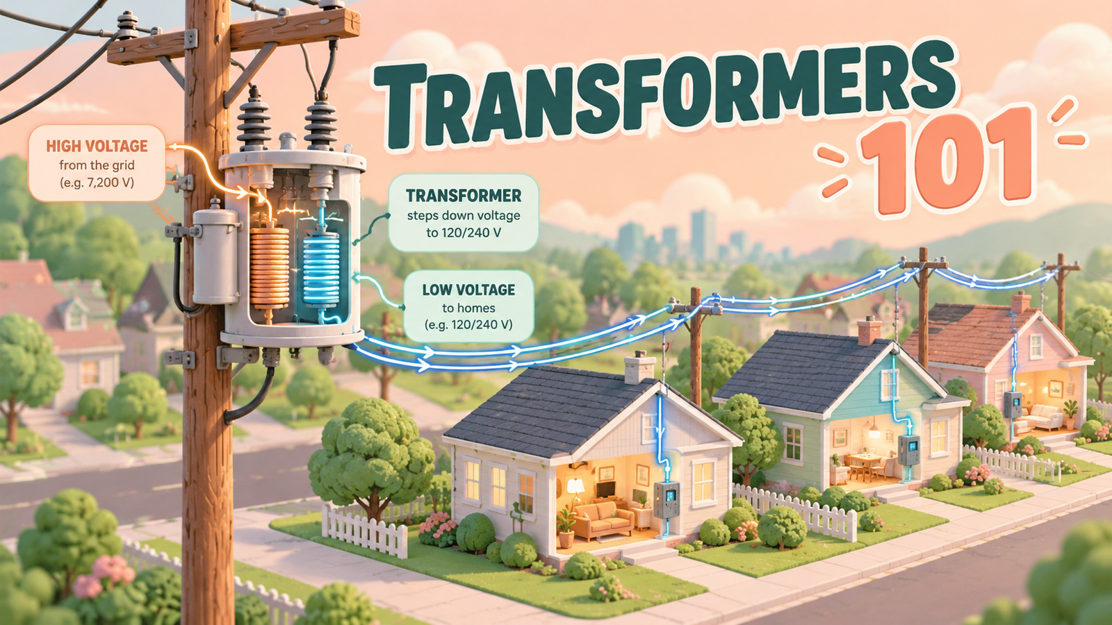
Energy Infrastructure · Transformers & Grid Assets
A distribution transformer steps medium voltage down to levels customers can use. This guide explains construction, operation, ratings, types, losses, protection, maintenance and grid applications for engineers, planners and asset managers.
A distribution transformer is the last major voltage-changing device between a utility’s medium-voltage network and the customers it serves. It sits quietly on a pole, on a concrete pad or inside a building. When it is sized, protected and maintained well, nobody notices it. When it is overloaded or fails, a whole street can lose power.
This guide explains how a distribution transformer is built and how it works, how to read its ratings, and how engineers and asset managers select, load, protect and maintain it. Numerical examples are illustrative, not universal design rules. Real requirements depend on the equipment design, manufacturer, jurisdiction and installation.
Introduction: Why Distribution Transformers Matter
Utilities move power at medium voltage because it is efficient, but customers cannot use that voltage directly. A distribution transformer bridges the gap at very large numbers of points across a network, and most units are energized around the clock.
- ReliabilityA failed unit interrupts every customer it supplies.
- Grid capacityThe rating often limits how much new load, such as EV charging or heat pumps, a street can accept.
- LossesCore losses continue day and night, so efficiency choices compound over decades.
- SafetyUnits contain high voltage, stored energy and, often, insulating liquid.
To see where these units fit in the wider system, read our guide to how power moves through generation, transmission and distribution networks.
What Is a Distribution Transformer?
A distribution transformer is a static electrical device that transfers AC energy between circuits through electromagnetic induction, with no moving parts. Its primary purpose is generally to reduce distribution-system voltage to a level suitable for end users. For example, a unit may convert 11 kV or 13.8 kV feeder voltage to 400/230 V or 240/120 V.
Applications and configurations vary. Some units supply customers at an intermediate medium voltage, provide galvanic isolation, or connect distributed generation. Others operate in step-up mode when power flows toward the network.
There is no universal boundary between distribution and power transformers. Many utilities place distribution units between a few kVA and roughly 2.5 to 3 MVA, but definitions differ.
How Does a Distribution Transformer Work?
An alternating current in the primary winding produces an alternating magnetic flux in the iron core. That flux links the secondary winding and induces a voltage in it. When a load is connected, secondary current flows, and the primary draws a matching current from the supply.
For an ideal transformer, voltage varies in proportion to the number of turns, so Vp / Vs = Np / Ns. Current varies inversely, so power in equals power out. Real units have small losses, and the actual ratio depends on winding design, connection and tap position.
Example (illustrative): a delta-star 11 kV / 400 V unit has a line-voltage ratio of 27.5:1. Its per-phase turns ratio is about 47.6:1, because each star-connected secondary winding sees 400 / √3 ≈ 231 V while each delta primary winding sees the full 11 kV. Always check whether a ratio refers to line voltages or winding turns.
The Role of Distribution Transformers in the Electricity Grid
A typical path runs from a substation transformer to a medium-voltage feeder, then to a distribution transformer, a low-voltage network, a service connection and finally the meter. The distribution transformer is where the low-voltage network begins. Our comparison of transmission and distribution networks shows how this stage differs from bulk transfer.
Within that chain the unit lowers voltage, separates the medium-voltage and low-voltage systems electrically, sets a capacity limit for the customers behind it, and shapes the low-voltage network through its location.
Practice differs by region. North American networks often use many small single-phase units, each serving a few customers over short secondary circuits. Networks in many other regions use fewer, larger three-phase units that feed longer low-voltage feeders.
Main Types of Distribution Transformers
Pole-mounted transformers
These hang from or sit on utility poles in overhead networks. Ratings are usually small, from a few kVA to a few hundred kVA depending on region, because the pole structure carries the weight.
Pad-mounted transformers
These sit on a concrete pad in a locked, tamper-resistant enclosure and are fed by underground cable. They suit residential subdivisions and commercial sites where overhead lines are not acceptable.
Ground-mounted and substation distribution transformers
Larger ground-mounted units, including those in compact secondary substations, are often packaged with medium-voltage switchgear and a low-voltage board. They serve apartment blocks, commercial buildings and industrial sites, and can be installed outdoors, in kiosks or in dedicated rooms.
Oil-immersed transformers
The core and windings sit in an insulating liquid, such as mineral oil or an ester fluid, that also carries heat to the tank surface. This is the most common design for outdoor utility use.
Dry-type transformers
These use solid insulation, such as cast resin or varnish-impregnated windings, and are cooled by air. They are common indoors, where fire safety or liquid containment is a concern.
Single-phase and three-phase transformers
A single-phase unit serves one or a few customers and is common on rural and residential lines in some regions, including split-phase 240/120 V supplies. A three-phase unit may be one three-limb core or a bank of three single-phase units. Banks allow partial replacement but need more space and careful matching.
Table 1: Distribution Transformer Types
| Type | Typical Installation | Common Applications | Key Considerations |
|---|---|---|---|
| Pole-mounted | On or beside utility poles, overhead networks | Rural and suburban residential supply | Weight limits, lightning exposure, access for crews, ambient conditions |
| Pad-mounted | Concrete pad, locked enclosure, underground cable feed | Subdivisions, small commercial sites | Tamper resistance, public safety, flooding, clearances, cable terminations |
| Ground-mounted or compact substation | Fenced yard, kiosk or electrical room | Apartment blocks, commercial and industrial sites | Space, noise, fire separation, containment, switchgear coordination |
| Oil-immersed | Mostly outdoors; some indoor vaults | Utility networks, outdoor customer sites | Fluid type, leak and fire management, periodic oil assessment |
| Dry-type | Indoors in ventilated rooms; enclosed outdoor versions exist | Buildings, hospitals, transport and industrial facilities | Ventilation, dust and moisture, insulation level limits, enclosure rating |
| Single-phase and three-phase | Any of the above | Single-phase for light loads; three-phase for larger or three-phase customers | Connection group, load balance, grounding, bank versus single unit |
Distribution Transformer Construction and Main Components
Magnetic core
The core is built from thin laminations of electrical steel, usually grain-oriented silicon steel, to carry flux while limiting eddy-current losses. Some high-efficiency designs use amorphous metal, which lowers no-load loss but can raise cost and size.
Primary and secondary windings
Windings are made of copper or aluminum. The high-voltage winding has many turns of smaller conductor, and the low-voltage winding has fewer turns of heavier conductor or foil. They must withstand the mechanical forces that short-circuit currents create.
Insulation system
Insulation combines solid materials, such as paper and pressboard, with liquid, resin or air. Insulation levels are chosen to suit the system voltage and expected lightning and switching surges. Thermal aging of solid insulation, accelerated by moisture and heat, is the main limit on service life.
Transformer oil, where applicable
In liquid-filled units the fluid insulates and cools. Mineral oil is common, while natural and synthetic esters offer higher fire points and better biodegradability. Older units in some regions may contain PCB-contaminated oil, so handling and disposal must follow local regulations.
Tank and enclosure
The tank is welded steel with corrugated walls or radiators to shed heat and absorb oil expansion. Larger units may have a conservator. Pad-mounted designs add a lockable enclosure with separate compartments, and coastal or polluted sites need suitable coatings.
Bushings and terminals
Bushings carry conductors through the tank wall while insulating them from it. They are made of porcelain or polymer, or replaced by cable boxes and separable connectors in underground designs. Cracks, tracking and leaking gaskets are common inspection points.
Cooling arrangements
Most distribution units rely on natural cooling, with heat leaving through tank surfaces. Larger or heavily loaded units may add fans. Dry-type units are cooled by natural or forced air and need adequate room ventilation.
Tap-changing arrangements
Most distribution units have an off-circuit tap changer that is adjusted only while the unit is de-energized. A range such as plus or minus 2 × 2.5 percent is common, but it depends on specification. On-load tap changers exist but are uncommon at this size.
Protective devices and accessories
Typical items include high-voltage fuses or cutouts, surge arresters, low-voltage fuses or breakers, pressure-relief devices, temperature and oil-level indicators, and grounding terminals. Larger units may have gas-actuated relays. Some designs are completely self-protected, with built-in protection devices.
Distribution Transformer Ratings Explained
Rated power in kVA
The kVA rating is apparent power capacity, not real power by itself. Real power depends on the load’s power factor, so kW = kVA × power factor.
Illustrative example: a 500 kVA three-phase unit rated 11 kV / 400 V can deliver about 722 A on the low-voltage side (500,000 / (√3 × 400)). The high-voltage current is about 26 A. At a 0.9 power factor, it supplies about 450 kW.
Voltage, frequency and phase configuration
Primary and secondary voltages define the transformation. Frequency, commonly 50 or 60 Hz, must match the system. Phase configuration and winding connection determine how the unit handles unbalanced loads, harmonics and earth faults.
Impedance
Impedance, expressed as a percentage, is the voltage needed to circulate rated current with the secondary shorted, relative to rated voltage. It affects fault current and voltage regulation. Higher impedance limits fault current but increases voltage drop under load.
Illustrative example: a 4 percent impedance on the 500 kVA unit above implies a theoretical maximum secondary fault current of about 18 kA (722 / 0.04), assuming an infinitely strong source. Real source impedance lowers this value.
Temperature rise and insulation considerations
Standards define permitted temperature rise above a reference ambient. Reference ambients, altitude limits and rise values depend on the standard, insulation system and fluid. Operation outside the stated service conditions, such as high ambient temperature or altitude above 1,000 m, usually calls for derating or a special design. Insulation level, often given as impulse and power-frequency withstand voltages, shows the surge strength.
Cooling classification
Under IEC naming, ONAN means oil with natural convection and natural air cooling, and ONAF adds fans. AN and AF describe air-cooled dry-type units. Other standards use different letter codes.
Applicable standards and nameplate information
Applicable standards depend on jurisdiction, equipment type and project specification. Common families include IEC 60076 for power transformers and the IEEE C57 series for liquid-immersed and dry-type units, alongside regional efficiency rules. Do not assume compliance without test reports or the nameplate and documentation to support it.
Table 2: Distribution Transformer Nameplate Ratings
| Rating or Parameter | Meaning | Why It Matters |
|---|---|---|
| Rated power (kVA) | Apparent power capacity under defined conditions | Basis for sizing and loading studies |
| Primary and secondary voltage | Rated line voltages of each winding | Must match the feeder and the customer supply |
| Frequency (Hz) | Rated supply frequency | Affects core flux and losses |
| Phases and connection group | Number of phases, winding connection and phase displacement | Determines parallel operation, grounding and unbalance handling |
| Tapping range | Available ratio adjustments | Compensates for feeder voltage levels |
| Impedance (%) | Short-circuit voltage at rated current | Sets fault current and voltage regulation |
| Temperature rise | Permitted winding and oil temperature rise | Links to insulation life and loading capability |
| Cooling class | Cooling method, such as ONAN or AN | Defines how heat leaves the unit |
| Insulation level | Impulse and power-frequency withstand values | Shows surge strength for the installation |
| Fluid type and quantity | Insulating liquid and mass or volume | Needed for containment, fire and environmental planning |
| Standard and year | Design standard the unit was built to | Indicates test and performance requirements |
| Manufacturer, serial number, year | Identification data | Supports records, warranty and failure analysis |
Common Distribution Transformer Configurations
The winding connection determines how the unit treats unbalanced loads, triplen harmonics and earth faults. Choices vary widely between utilities and countries, so the table below shows typical examples rather than rules.
| Configuration | Typical Use | Notes |
|---|---|---|
| Delta-star with neutral (for example Dyn11) | Three-phase supply in many IEC-based networks | Delta winding circulates triplen harmonics and keeps low-voltage earth faults from affecting the medium-voltage system as directly |
| Star-zigzag (for example Yzn11) | Networks with unbalanced low-voltage loading | Zigzag secondary copes well with unbalance, though design and cost vary |
| Single-phase, center-tapped secondary | North American residential supply at 240/120 V | Two secondary windings in series provide split-phase service |
| Grounded-star to star (for example 208Y/120 V or 480Y/277 V) | Commercial and industrial supply in North America | Provides line-to-neutral loads; connection depends on utility practice |
How to Select a Distribution Transformer
Selection starts with demand and ends with a lifecycle view. Engineers should account for expected demand, voltage, phase configuration, environment, protection and applicable standards, then compare options on total cost of ownership.
- Demand: estimate diversified demand per customer, then add allowance for growth, EV charging, heat pumps and rooftop solar.
- Voltage and taps: match the feeder and customer voltages, and confirm the tapping range covers expected variation.
- Phase and connection: choose single-phase or three-phase and a connection group suited to unbalance, harmonics and grounding.
- Environment: consider ambient temperature, altitude, pollution, flooding, indoor or outdoor placement and fire rules.
- Type and fluid: compare oil-immersed and dry-type options, and the liquid where relevant (Table 3).
- Impedance and fault level: check the result against low-voltage protection ratings and voltage drop limits.
- Efficiency: evaluate no-load and load losses over the expected life, and check local efficiency regulations.
- Protection: confirm fuse, arrester and breaker coordination.
Table 3: Oil-Immersed vs. Dry-Type Transformers
| Aspect | Oil-Immersed | Dry-Type |
|---|---|---|
| Typical applications | Utility networks and outdoor sites | Indoor sites such as buildings, hospitals and transport facilities |
| Insulation and cooling | Solid insulation plus insulating liquid; heat moves by liquid circulation to tank or radiators | Solid insulation such as cast resin; cooled by natural or forced air |
| Installation considerations | Needs containment, clearances and fire protection suited to the fluid | Needs ventilation, clean and dry surroundings and enclosure suited to location |
| Maintenance needs | Visual checks, leak checks and oil assessment on larger or critical units | Cleaning, thermal checks of windings and inspection of connections and ventilation |
| Limitations | Fluid leaks, fire management and disposal considerations | Often larger for equal rating, may have lower available voltage or insulation levels, sensitive to contamination and condensation |
Neither type is universally better. The right choice depends on location, codes, loading, budget and the owner’s maintenance capability.
Distribution Transformer Applications
- Residential distributionPole-mounted and pad-mounted units supply homes, with low-voltage feeders sized for diversified demand.
- Commercial buildingsOffices and shopping centers use pad-mounted, kiosk or indoor dry-type units, often with metering at the low-voltage board.
- Industrial facilitiesFactories use higher-rated units, sometimes with special designs for harmonic-rich or motor loads.
- Rural electrificationSingle-phase pole units on long feeders can reach scattered customers economically, but voltage regulation needs care.
- Renewable energy and distributed generationUnits connect solar and storage to the network, and may see reverse power flow and inverter harmonics.
- Utility distribution networksFleets of units form the backbone of the low-voltage network, supported by switching and protection.
Transformer Loading, Capacity and Voltage Regulation
The kVA rating applies under defined conditions. Actual loading capability depends on ambient temperature, cooling, installation conditions, operating profile and manufacturer guidance. Insulation ages with winding hot-spot temperature, so a brief peak may do little harm while sustained heavy loading consumes life faster. Loading guides such as IEC 60076-7 and IEEE C57.91 describe how to assess this, and the manufacturer’s overload advice should take precedence for a specific unit.
Voltage regulation is the change in secondary voltage between no load and load. For a lagging power factor it is approximately %R × cosφ + %X × sinφ, where %R and %X are the resistive and reactive parts of impedance. Higher impedance and lower power factor give larger voltage drop.
Distribution Transformer Losses and Efficiency
Losses include core losses and winding losses, and their relative importance varies by design and operating conditions.
| Loss Type | Cause | Behavior | Typical Mitigation |
|---|---|---|---|
| Core (no-load) loss | Magnetizing the core: hysteresis and eddy currents | Present whenever energized; roughly constant | Better core steel, amorphous cores, avoiding oversizing |
| Winding (load) loss | Current flowing through winding resistance | Rises with the square of current | Larger conductors, load balancing, adequate capacity |
Modern units typically exceed 98 percent efficiency at rated load, though this varies with size and design. Peak efficiency occurs when load losses equal no-load losses. Because many distribution transformers carry modest average load, no-load loss often dominates energy lost over a year.
Illustrative example: a unit with 300 W of no-load loss wastes about 2,628 kWh a year (0.3 kW × 8,760 h), regardless of load. Doubling current roughly quadruples winding loss. For this reason, utilities often evaluate purchases by capitalizing losses, and many regions set minimum efficiency rules.
Common Faults and Failure Causes
Failures rarely have one cause. Typical contributors include sustained overloading, insulation aging and moisture, lightning and switching surges, through-faults that stress windings, loose connections, bushing damage, oil leaks, animal contact, vandalism and flooding. Our overview of what causes power grid failures shows how equipment faults fit into wider outage patterns.
Table 4: Common Problems and Warning Signs
| Potential Problem | Possible Indicators | Appropriate Assessment or Response |
|---|---|---|
| Overloading or thermal stress | High load readings, elevated temperature, accelerated oil darkening | Review load profile and ambient conditions; consider load transfer or capacity upgrade |
| Insulation deterioration or moisture | Poor insulation test results, unusual oil test values, tripping events | Arrange qualified testing and oil analysis where applicable |
| Internal fault or partial discharge | Unusual noise, gas indications, protection operation | De-energize per procedure; do not re-energize repeatedly without assessment |
| Oil leak or low level | Staining, wet gaskets, low level gauge | Inspect source, assess environmental risk, schedule repair |
| Bushing or termination problem | Cracks, tracking marks, discoloration, flashover marks | Qualified inspection; replace damaged parts under approved procedures |
| Loose connection or hot spot | Discoloration, local heating seen by thermal imaging, voltage complaints | Thermography from a safe distance; tighten or repair only under safe isolation |
| Surge damage | Failed arrester, flashover marks after storms | Check surge protection and grounding; test before returning to service |
| Cooling or ventilation blockage | Blocked fins, vegetation, dust, higher temperatures at normal load | Clear access and airflow safely; review location |
These indicators are warning signs, not definitive diagnoses. Several conditions can produce the same symptom, so confirmation requires qualified inspection and testing.
Inspection, Testing and Maintenance
All installation, testing and maintenance work must be done by qualified personnel using approved procedures, safe isolation, lockout and tagout, proper grounding and the applicable electrical safety requirements. Never open a tank, remove covers or bypass protection on energized equipment. Actual schedules depend on manufacturer instructions, applicable standards, utility policy and operating conditions.
Table 5: Maintenance and Monitoring Checklist
| Activity | Typical Focus | Notes |
|---|---|---|
| Visual inspection | Tank condition, corrosion, leaks, enclosure integrity, signage, clearances | Performed from safe distances unless isolated |
| Loading review | Peak and average load against rating, phase balance, growth trend | Uses SCADA, AMI or load survey data where available |
| Temperature trends | Top-oil or winding temperature compared with load and ambient | Trends reveal changes that single readings may miss |
| Oil assessment, where applicable | Level, moisture, dielectric strength, dissolved gases | Practical for larger or critical units; sealed small units may not allow sampling |
| Connections and bushings | Cracks, tracking, tightness, thermal condition | Corrective work only under safe isolation |
| Cooling equipment | Fins, fans, ventilation openings, room airflow | Check that nothing obstructs heat dissipation |
| Protection checks | Fuses, arresters, low-voltage breakers, grounding | Verify ratings and coordination with current network conditions |
| Inspection records | Dates, findings, test results, nameplate data | Good records support condition assessment and replacement planning |
| Qualified testing | Insulation resistance, winding resistance, turns ratio, other tests as specified | Test choice depends on size, criticality, standard and manufacturer advice |
Distribution Transformers and Smart Grid Technologies
In a smart grid, distribution transformers become measurable points rather than silent assets. Utilities that link smart meters to transformers can estimate transformer loading from customer data. This is one practical use of advanced metering infrastructure (AMI).
The same data can flag overloaded units and uneven phase loading. Accuracy depends on correct meter-to-transformer records, time synchronization and the share of load that is metered. Smart monitoring can improve operating visibility, but it does not replace engineering assessment or maintenance. Wider power system automation then links these insights to switching and control decisions.
Digital Monitoring, Sensors and Predictive Maintenance
Sensors can measure load current, voltage, temperature, oil level, pressure, moisture, dissolved gases and partial discharge. Full online monitoring is more common on large or critical units, while fleet-wide visibility for small units often comes from AMI data and periodic inspection.
Collected data is only useful once a baseline exists. Analytics can then flag trends, such as temperature rising at constant load. Machine learning may support anomaly detection and health scoring, as discussed in our guide to AI in smart grids, and the sensors and IoT devices article explains the data side. Limits include false alarms, poor data quality and unclear thresholds. An alert should prompt engineering review, not automatic action.
Practical Illustrative Scenarios
The four scenarios below are illustrative, not real-world case studies. Their numbers are assumptions chosen to show the reasoning.
Scenario 1: Selecting a transformer for a growing residential area (illustrative)
Situation: A phased development plans 150 homes with possible EV chargers and rooftop solar.
Considerations: Assuming 2.5 kVA diversified demand per home gives about 375 kVA. Allowance for EVs and heat pumps might lift planning demand toward 450 kVA. Oversizing raises no-load loss and cost, while undersizing shortens life and limits growth. Low-voltage feeder length and voltage drop also matter.
Possible actions: Compare one 500 kVA unit with two smaller units placed closer to loads. Check impedance against low-voltage fault ratings, and consider staged installation.
Limitations: Diversified demand varies greatly by climate, heating type and region. Standard sizes also differ between markets.
Scenario 2: Reviewing a transformer with high peak loading (illustrative)
Situation: A 500 kVA unit shows 540 kVA peaks lasting two to three hours on hot evenings.
Considerations: That is 108 percent of nameplate, but impact depends on ambient temperature, preceding load, cooling condition and the unit’s thermal design. Loading guides and manufacturer advice show whether such peaks are acceptable.
Possible actions: Verify measurement accuracy, review a year of load data, check temperature indicator history, and look for obstructed cooling. Options include phase rebalancing, load transfer or planned capacity upgrade.
Limitations: Meter-derived loading may miss unmetered load and losses. Without temperature data, insulation life consumption cannot be determined reliably.
Scenario 3: Assessing abnormal temperature or oil-related indicators (illustrative)
Situation: A pad-mounted oil-immersed unit shows a high temperature reading at moderate load, and staining appears near a bushing gasket.
Considerations: Possible explanations include instrument error, blocked cooling, a leak lowering oil level, moisture ingress, a loose connection or an internal problem. One reading cannot separate these.
Possible actions: Record the finding, compare with similar units, and arrange qualified inspection under safe isolation. Oil sampling and dissolved gas analysis can follow where the design and unit size justify it. Utility procedure determines whether to continue, derate, repair or replace.
Limitations: Many small sealed units cannot be sampled economically. Field repairs and tank access must be left to qualified personnel.
Scenario 4: Choosing between oil-immersed and dry-type equipment (illustrative)
Situation: A new commercial building needs a 1,000 kVA supply, with a basement electrical room or an outdoor yard as options.
Considerations: An outdoor oil-immersed unit needs containment, fire separation and noise control. A cast-resin dry-type unit indoors needs ventilation and heat removal, and offers lower fluid-related fire load. Flood risk, access for replacement, building codes and maintenance capability also matter.
Possible actions: Compare options on lifecycle cost, space, safety codes and utility requirements, then consult the authority having jurisdiction.
Limitations: Neither option is universally better. Local codes may favor one, and ventilation or containment design needs project-specific calculation.
Challenges in Distribution Transformer Planning and Operation
Aging fleets
Many units have been in service for decades, with incomplete records.
Load growth
EV charging, heat pumps and electrified industry can push local transformers past their ratings before the wider network is stressed.
Distributed generation
Rooftop solar can cause reverse power flow and voltage rise on low-voltage feeders, and inverters add harmonics.
Data quality
Wrong meter-to-transformer links, missing nameplate data and sparse measurements limit analysis.
Environment and climate
Heat waves, flooding, pollution and wildfire smoke affect cooling and insulation, and fluid spills raise environmental duties.
Best Practices for Asset Management and Reliability
- Keep an accurate register with nameplate data, location, connected customers, age and test history.
- Review loading regularly using actual measurements, and plan reinforcement before limits are reached.
- Match effort to criticality: simple inspection for small units, deeper condition assessment for large or critical ones.
- Use risk-based prioritization that combines condition, consequence of failure and loading.
- Specify efficiency and total cost of ownership in procurement, not just purchase price.
- Follow manufacturer instructions, applicable standards and utility policy for testing and maintenance.
- Train crews, and enforce safe isolation and approved procedures.
- Validate analytics outputs with engineering review before acting on them.
Future Trends in Distribution Transformers
The pace of change differs by region, and some developments are still emerging.
- Higher efficiencyTighter regulation and amorphous or improved core materials reduce no-load loss.
- Ester fluidsNatural and synthetic esters are used more widely where fire safety and biodegradability matter.
- Grid-edge readinessDesigns and planning increasingly account for EVs, storage and solar.
- Solid-state transformersPower-electronics-based designs offer controllability, but remain emerging and costly for most distribution uses.
Key Takeaways
- A distribution transformer transfers AC energy through electromagnetic induction and usually lowers distribution voltage for end users.
- Voltage transformation depends on the winding turns ratio and design.
- kVA is apparent power capacity, not real power by itself.
- Loading capability depends on ambient temperature, cooling, installation and operating profile.
- Impedance affects both fault current and voltage regulation.
- Core and winding losses both matter, and their balance varies with design and operation.
- Selection should weigh demand, voltage, phase configuration, environment, protection and standards.
- Monitoring improves visibility but does not replace engineering assessment or maintenance.
Conclusion
A distribution transformer looks simple, yet it combines electromagnetic design, insulation science, thermal management and protection engineering in one compact asset. Understanding its construction and ratings makes it easier to size units, avoid avoidable losses and recognize early warning signs.
As load patterns change with electrification and distributed energy, local transformers increasingly set grid capacity limits. Utilities that combine sound engineering, good records, safe maintenance and selective digital monitoring will keep these assets reliable.
Frequently Asked Questions
What is a distribution transformer?
A distribution transformer is a static device that transfers AC energy between circuits by electromagnetic induction. It usually reduces medium-voltage distribution voltage to the level used by homes, businesses and small industrial customers.
How does a distribution transformer work?
Alternating current in the primary winding creates alternating flux in the core, which induces voltage in the secondary winding. The voltage ratio depends mainly on the turns ratio and winding connection.
Why is a distribution transformer important?
It supplies power at a usable voltage and sets the capacity for the customers behind it. Its loading, losses and condition influence reliability, voltage quality and network costs.
What are the main components of a distribution transformer?
Main components are the magnetic core, primary and secondary windings, insulation system, tank or enclosure, bushings and terminals, and protective devices. Liquid-filled units also contain insulating oil, and some have cooling fans or tap changers.
What challenges affect distribution transformers?
Common challenges include aging, overloading from load growth, reverse power flow from distributed generation, harmonics, environmental stress and limited condition data.
Where are distribution transformers used?
They are used in residential areas, commercial buildings, industrial sites, rural networks, renewable energy connections and throughout utility distribution systems, mounted on poles, on pads, in kiosks or indoors.
Have a question about power systems?
Questions about this topic or ideas for future articles? Get in touch.
Contact Us
I share real stories, practical ideas and honest perspectives on business, marketing and life. This blog is a space to learn, grow and connect.