Data Centers & Electricity · AI Data Center Energy
Data center backup power is a coordinated architecture, not a single device. This guide explains how UPS systems, generators, energy storage, transfer equipment, distribution and monitoring work together, and where the risks lie.
A data center cannot treat a utility interruption as a minor event. Servers, storage, networking and cooling all depend on continuous electricity, so data center backup power must be engineered as a complete system, not bought as a single product.
Introduction: Why Backup Power Needs Careful Engineering
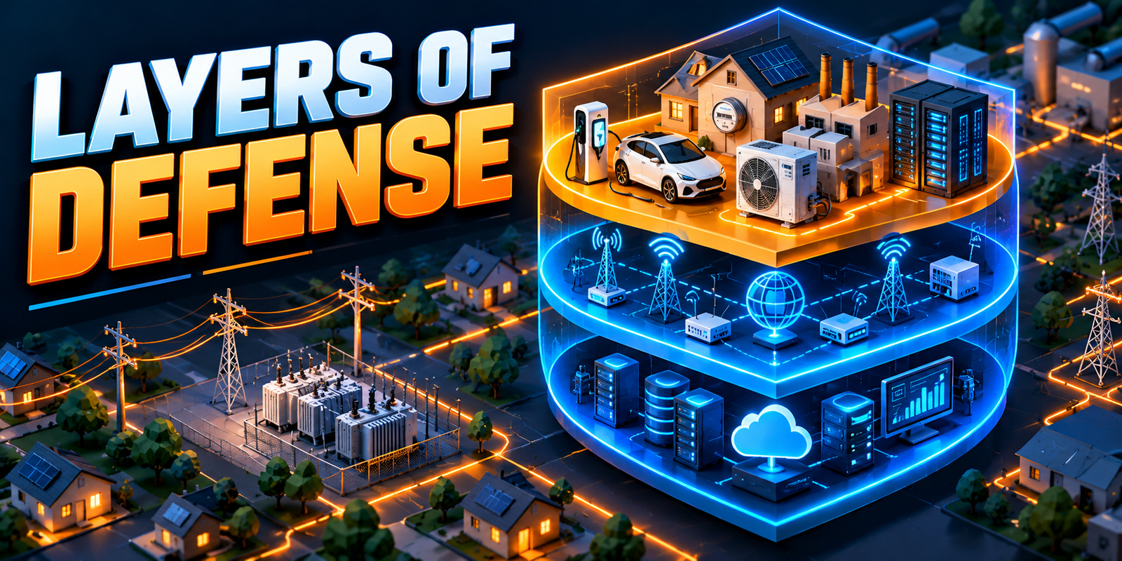
UPS systems, standby generators, energy storage, transfer equipment, electrical distribution and monitoring each perform a different function. A UPS bridges the first moments of a disturbance. Generators supply energy over longer periods. Transfer and control equipment decides which source feeds the load. Distribution and protection carry power safely, and monitoring shows what is happening.
These pieces only help if they are coordinated. This article explains each element, how they interact, and what can go wrong. It uses no performance figures or uptime claims, because the right design depends on the facility, its loads, its utility connection and applicable codes.
What Is Data Center Backup Power?
Data center backup power is the set of systems that keeps critical loads supplied when the normal utility supply is interrupted, disturbed or taken out of service. The normal supply is the utility connection, usually through transformers and switchgear. Backup power is a designed alternative that takes over, in whole or in part, when that supply is not available.
Two time scales matter. Ride-through covers very short interruptions and the transition between sources, typically handled by a UPS and its stored energy. Longer-duration supply covers extended outages, typically handled by standby generation or another designed source. Together, they let the facility respond to a disturbance in an orderly way.
Backup power does not, by itself, guarantee uninterrupted service. Outcomes depend on design, integration, maintenance, operating procedures and the nature of the event.
Why Backup Power Matters for Data Centers
IT equipment is only one dependent load. Cooling, controls, lighting, security and network gear also need power, and many IT systems cannot ride through even short interruptions without a bridge. An interruption can cause service disruption, data handling problems, equipment stress and recovery work, and the effects vary by workload and architecture.
AI data centers and other high-density computing environments raise the stakes. Concentrated loads demand careful electrical capacity and thermal-management planning, because cooling must also remain available when power sources change. Our overview of what causes power grid failures explains the supply-side disturbances that backup systems are designed to handle.
No single configuration suits every facility. Backup architecture should reflect operational requirements, load profiles, maintenance needs and acceptable risk.
Cooling deserves particular attention. Chillers, pumps, fans and control systems have their own power needs and their own restart behavior after a source change. If cooling recovers more slowly than the IT load, temperatures can rise quickly in dense environments, so backup planning should treat mechanical and electrical systems together.
Main Components of a Data Center Backup Power System
Table 1: Backup Power Components and Their Functions
| Component | Main Function | Typical Role in Backup Power | Key Planning Consideration |
|---|---|---|---|
| UPS | Supplies and conditions power to protected loads | Ride-through and transition between sources | Capacity, architecture, battery condition, coordination with other sources |
| Batteries and other storage | Store energy for the UPS or other uses | Provide the energy during short interruptions | Energy versus power, ageing, temperature, safety |
| Standby generators | Convert fuel energy to electricity | Longer-duration supply | Start reliability, fuel, emissions, noise, permits |
| Transfer equipment | Switches loads between sources | Automatic or static transfer where used | Transfer logic, timing, protection coordination |
| Switchgear, breakers, protection | Route, isolate and protect circuits | Enable the designed power paths | Fault levels, selectivity, maintainability |
| Transformers and distribution | Step down and distribute power | Carry power from sources to loads | Capacity, loading, location, common failure points |
| Fuel and generator support | Store and deliver fuel, cooling, starting and ventilation for generators | Keep generators ready and running | Storage, replenishment, contamination, local rules |
| Monitoring, controls, alarms, logs | Show status and record events | Support operation and later analysis | Alarm clarity, response procedures, data quality |
| Cooling and auxiliary loads | Remove heat and support operation | Must stay available through source changes | Often overlooked in backup planning |
Table 2: UPS, Generators and Energy Storage Compared
| Technology | Primary Function | Typical Response Role | Main Limitations |
|---|---|---|---|
| UPS | Conditioned power and ride-through | Immediate support during disturbances and transfers | Limited stored energy; does not supply long outages by itself |
| Generator | Longer-duration energy supply | Starts and takes load after a delay | Not instantaneous; depends on fuel, maintenance and transfer |
| Energy storage (battery systems) | Store and release electrical energy | Ride-through, load management, some microgrid roles | Finite energy; performance depends on condition, temperature and controls |
How UPS Systems Work in Data Centers
A UPS sits between the incoming supply and protected loads. During a short interruption, or while another source is starting and transferring, it can keep supplying the load from stored energy. A UPS also conditions power, which is separate from stored-energy capability. A unit can provide good conditioning with limited ride-through energy.
Common concepts include online or double-conversion designs, which continuously pass power through a rectifier and inverter, and other configurations such as line-interactive or standby types. Some designs use flywheel or other storage. Not every architecture suits every facility, and choice depends on load, criticality, space and efficiency goals. Standards such as IEC 62040 describe UPS performance and test methods.
Runtime depends on battery condition, load and operating assumptions, so it should be verified with the manufacturer rather than assumed. Maintenance, monitoring and testing keep those assumptions valid. The UPS must also be coordinated with transfer equipment and generators so that handoffs are stable.
Most designs also include bypass paths. A static bypass can transfer load around the UPS electronics under defined conditions, and a maintenance bypass lets technicians service the unit while the load stays supplied from another path. These paths add flexibility, but they also create operating states that need clear procedures, because a load on bypass is no longer protected in the same way.
Backup Generators and Longer-Duration Supply
Standby generators supply energy over a longer period than any battery bridge can. They differ from UPS systems because they are not instantaneous. They must start, stabilize and be connected to the load, which is why the UPS covers the gap.
At a high level, a generator system involves start signals, stabilization, transfer, and staged or controlled load acceptance. Fuel or energy availability, storage and replenishment constrain how long a facility can operate. Emissions, noise, permitting and local requirements affect where and how often a generator can run, and standards such as NFPA 110 or ISO 8528 may apply depending on jurisdiction.
Generators must be coordinated with UPS equipment, protection systems and facility loads. A generator that exists on paper is not the same as one that is ready. Readiness depends on design, integration, maintenance and operating procedures.
Larger sites may use several generators connected through paralleling switchgear, which lets units share load and adds flexibility but also adds control complexity. Fuel quality, starting systems, cooling, exhaust and ventilation all affect whether a unit performs when called on. Periodic running under suitable load conditions, planned with safety in mind, helps reveal problems that a no-load start can miss.
Batteries and Energy Storage for Data Center Resilience
Batteries inside UPS systems are the most common form of storage. Some sites also use separate battery energy storage systems, which may support ride-through, load management or selected microgrid arrangements.
Two ideas should be kept apart. Energy capacity describes how much energy can be stored, while power capability describes how fast it can be delivered. Performance depends on load, operating mode, usable capacity, degradation, temperature and control settings.
Lead-acid and lithium-ion are the best-known technologies, and other options exist. Each has trade-offs in footprint, maintenance, lifecycle and safety, which should be judged for the project rather than assumed. Safety, monitoring and fire-protection requirements for battery rooms depend on the technology and jurisdiction, and standards such as NFPA 855 or UL 9540 may be relevant.
Some operators also explore using storage for functions beyond ride-through, such as managing peak demand or supporting the grid. These uses can compete with the reserve role, because energy used for one purpose is not available for another. Any such arrangement needs clear operating limits, control logic that protects the backup reserve and agreement with the utility where required.
How Backup Power Systems Work Together
A typical conceptual sequence follows. Actual sequences vary by design, controls, equipment and operating conditions, and not every facility follows exactly this order.
Table 3: Typical Backup Power Response Sequence
| Stage | Equipment or System Involved | Purpose | Important Consideration |
|---|---|---|---|
| 1. Normal operation | Utility supply, transformers, switchgear, UPS | Supply the facility and keep batteries ready | Monitoring should confirm that backup systems are ready |
| 2. Disturbance support | UPS and protected loads | Support loads during the disturbance, depending on design | Support depends on load and battery condition |
| 3. Detection and control | Transfer and control systems, protection | Coordinate the response | Settings and logic must match the design |
| 4. Alternative source start | Standby generator or other source | Make another source available | Starting conditions and fuel readiness |
| 5. Transfer to the alternative source | Transfer equipment, distribution | Supply load through the designed path once conditions are met | Load acceptance and stability |
| 6. Return to normal | Utility, transfer and control systems, operators | Restore the normal supply under approved procedures | Avoid unplanned transfers; verify the utility is stable |
Understanding Backup Power Redundancy
Redundancy describes how much capacity or how many paths exist beyond what the load needs. N means the capacity needed to carry the load with no spare. N+1 adds one extra unit of capacity. 2N provides two complete systems.
Table 4: N, N+1 and 2N Redundancy Concepts
| Approach | General Meaning | Potential Benefit | Important Limitation |
|---|---|---|---|
| N | Capacity matched to the load | Simplest and lowest cost | No spare capacity when equipment is unavailable |
| N+1 | One additional unit beyond the required capacity | Tolerates loss or maintenance of one unit | Shared paths or components may still be a single point of failure |
| 2N | Two independent systems, each able to carry the load | Can allow maintenance and some failures without losing supply | Higher cost and complexity; independence must be real |
Redundant components are not the same as independent power paths. Common points of failure, such as shared switchgear, controls or fuel supply, can defeat apparent redundancy. Capacity must also be checked when equipment is unavailable for maintenance. A label alone does not prove fault tolerance or a particular uptime level, so the overall architecture matters more than the name.
Maintenance is part of the same question. A design that can carry the load only while every component is in service may have to accept more risk during planned work. Concurrent maintainability, meaning the ability to service equipment without interrupting the load, is a design goal some facilities adopt. It should be confirmed against the actual configuration rather than assumed from the redundancy label.
Backup Power, Grid Reliability and Utility Coordination
In many designs, backup systems complement the utility connection rather than replace it. Utility outages, disturbances, restoration and planned maintenance all shape operating plans. Backup generation does not remove the need for utility coordination or applicable approvals.
The data center’s expected demand, connection arrangement and backup architecture interact. Protection must be coordinated so that backup sources do not feed the utility network unsafely. Our guides to how power moves through generation, transmission and distribution networks and transmission versus distribution show where a facility connects. Site teams should document operating assumptions, responsibilities and communication paths with the utility.
Planned utility maintenance is a useful reminder that backup systems are also used deliberately. A scheduled outage on a feeder may require the facility to operate on generation for a period, with coordinated notice, clear start and end conditions and agreed contacts. Treating these events as rehearsed procedures, rather than rare emergencies, makes unplanned events easier to handle.
Common Backup Power Challenges
Table 5: Common Backup Power Challenges and Risk-Reduction Approaches
| Challenge | Possible Consequence | Practical Risk-Reduction Approach |
|---|---|---|
| UPS battery degradation or wrong runtime assumptions | Less ride-through than expected | Battery monitoring, inspection and verification of assumptions |
| Generator starting or transfer problems | Source unavailable when needed | Readiness checks and integrated testing |
| Fuel or energy availability limits | Reduced operating duration | Fuel planning, replenishment arrangements and monitoring |
| Undetected single points of failure | One fault affects several paths | Architecture review and failure-mode analysis |
| Poor coordination among UPS, generators, controls and distribution | Unstable or failed transfer | Coordination studies and commissioning tests |
| Inadequate maintenance or testing | Hidden defects | Planned maintenance and documented testing |
| Wrong load forecasts or expansion assumptions | Overloaded backup capacity | Regular capacity reviews and change control |
| Weak monitoring and alarm response | Late or missed warnings | Clear alarms, response procedures and training |
| Overlooked cooling and auxiliary loads | Heat problems despite IT power | Include them in backup design and testing |
| Safety, environmental and permit requirements | Delays or restrictions | Early engagement with authorities |
No single measure removes all of these risks. They are managed through layered design, testing and operating discipline.
Testing, Maintenance and Operational Readiness
Readiness comes from planned maintenance, realistic testing and clear procedures. Testing individual components is not the same as validating the complete system, because many failures occur at interfaces between components. Integrated systems testing checks that sources, transfer, protection and loads behave together.
Test planning must address safety, load considerations and change control. Intervals and methods should come from manufacturer instructions, applicable standards, authority requirements and facility policy, not from generic rules. All work must be done by qualified personnel using approved procedures. Protection systems must never be bypassed.
Table 6: Maintenance, Testing and Monitoring Considerations
| Area | Typical Focus | Note |
|---|---|---|
| Preventive maintenance planning | Scheduled work for all backup equipment | Intervals follow manufacturer, standards and policy |
| UPS and battery inspection | Condition, connections, environment, alarms | Battery condition drives actual runtime |
| Generator testing and readiness | Starting, fuel, cooling, controls, loading | Test method and load must be planned for safety |
| Transfer and protection testing | Settings, logic, operation under controlled conditions | Requires qualified personnel and procedures |
| Integrated systems testing | Full-system response to simulated disturbances | Planned with risk controls and change control |
| Monitoring and alarm review | Alarm history, nuisance alarms, trends | Alarms need defined responses |
| Procedures and training | Operating, emergency and recovery steps | Keep current as the facility changes |
| Issue tracking | Recording defects and confirming corrective actions | Closes the loop on findings |
Monitoring, Automation and AI-Based Analytics
Monitoring tells teams whether backup systems are ready. Useful sources include electrical metering, UPS and battery monitoring, generator and transfer-equipment status, and facility monitoring or SCADA systems. Alarm management and event logs help teams respond and analyze events afterward. Our articles on sensors and IoT in grid operations and power system automation explain the underlying monitoring concepts.
Asset-health analytics and AI or machine learning can help flag anomalies and trends, for example a battery string drifting from its normal behavior, as covered in AI in smart grids. Limits apply. Models depend on data quality, can raise false alarms and cannot replace qualified engineering review or guarantee failure prevention.
Alarm management deserves its own attention. Too many alarms hide the important ones, while too few leave gaps. Each alarm should have a defined meaning, an owner and an expected response. Event logs should be time-synchronized so teams can reconstruct the order of events across UPS, generator, transfer and utility systems after a disturbance.
A Hypothetical Data Center Backup Power Scenario
This is a hypothetical example, not a real event. It uses no figures and no real utilities, and it simplifies a real facility.
A data center normally takes power from the utility through transformers and switchgear, with a UPS feeding protected IT loads. A disturbance on the utility feeder causes the incoming supply to fail. The UPS supports protected loads while transfer and control systems detect the loss and signal standby generation to start.
When the generator is available and conditions are met, transfer equipment connects it to the designed path, and load is picked up in the sequence the design allows. Operators watch alarms and event logs, confirm cooling remains available and follow documented procedures. When the utility returns and is judged stable, the site returns to normal supply under approved steps.
Assumptions and limitations: the example assumes the UPS batteries are in good condition, the generator is ready, fuel is available, and settings and procedures have been tested together. If any one is missing, the outcome could differ. This is why planned testing and recovery procedures matter, and why the example cannot be taken as evidence of any specific result.
Best Practices for Data Center Backup Power Planning
Table 7: Backup Power Planning Checklist
| Planning Area | Key Question | What to Document |
|---|---|---|
| Critical loads | Which loads must stay powered, and for how long? | Load list and operating requirements |
| Grid connection | What outage and disturbance assumptions apply? | Connection arrangement, utility assumptions |
| UPS approach | Which architecture suits the load and risk? | Selection rationale, runtime assumptions |
| Energy storage | What energy and power are needed? | Capacity basis, safety plan |
| Backup generation | Is longer-duration supply required? | Sizing basis, fuel plan, permits |
| Transfer and protection | Are controls and protection coordinated? | Coordination study, settings |
| Redundancy | Where are common points of failure? | Architecture review results |
| Maintenance and commissioning | How will readiness be proven and kept? | Test plans, schedules, records |
| Monitoring | How are condition and alarms tracked? | Alarm list, response procedures |
| Recovery procedures | Who does what during and after an event? | Response and recovery documents |
| Growth | How will expansion affect backup capacity? | Capacity reviews, change control |
| Safety and regulation | Which requirements apply? | Applicable codes, approvals |
The Future of Data Center Backup Power
Several developments are worth watching, and they differ in maturity. Battery energy storage is established in UPS roles and is expanding into broader uses. Microgrid arrangements, which combine local generation, storage and controls, are used in some facilities and remain project-specific. Digital monitoring and predictive maintenance are increasingly common but depend on data quality.
Flexible demand and closer coordination with grid operators are emerging, especially where utilities face capacity limits. Our guide to the smart grid shows how that coordination is developing. Adoption will depend on local rules, economics and reliability requirements, so predictions should be treated cautiously.
Conclusion
UPS systems, generators, energy storage, transfer equipment, distribution design, monitoring and maintenance each contribute a different function to data center resilience. Effective data center backup power comes from coordinating them, not from any one device or redundancy label.
The most reliable approach is to design the complete system around the facility’s requirements, then test it as a whole and keep testing it as loads and equipment change. Even then, no design can promise uninterrupted service.
Frequently Asked Questions
What is data center backup power?
It is the set of systems, such as UPS equipment, generators, energy storage, transfer equipment and distribution, that keeps critical loads supplied when the utility supply is interrupted or disturbed.
How does data center backup power work?
A UPS typically supports loads during the first moments of a disturbance, while control systems start and transfer to a standby generator or other source. The actual sequence depends on the design.
Why is data center backup power important?
IT, cooling and network equipment depend on continuous power. Backup systems limit the effect of utility interruptions, though they cannot guarantee uninterrupted service.
What are the main components of data center backup power?
Main components include UPS systems, batteries or other storage, standby generators, transfer equipment, switchgear and protection, transformers and distribution, fuel support, monitoring and controls, and cooling for auxiliary loads.
What are the challenges of data center backup power?
Common challenges include battery degradation, generator start or transfer problems, fuel limits, hidden single points of failure, poor coordination, inadequate testing, wrong load forecasts, weak monitoring and permit requirements.
Where is data center backup power used?
It is used across enterprise, colocation, cloud and AI data centers, and in related facilities such as network and telecom sites. Configurations differ by facility.
What is the difference between a UPS and a backup generator?
A UPS responds immediately from stored energy and conditions power, but supports loads for a limited time. A generator takes time to start but can supply energy for longer, subject to fuel.
How do batteries support data center backup power?
Batteries provide the stored energy that lets a UPS carry loads through short interruptions and transfers. Their performance depends on condition, load, temperature and controls.
Do backup generators eliminate the risk of power interruption?
No. Generators must start, transfer and run correctly, and they depend on fuel, maintenance and integration. Risk is reduced, not removed.
How often should a data center test its backup power systems?
There is no universal interval. Testing frequency and method should follow manufacturer instructions, applicable standards, authority requirements and the facility’s risk policy.
Have a question about power systems?
Questions about this topic or ideas for future articles? Get in touch.
Contact Us
I share real stories, practical ideas and honest perspectives on business, marketing and life. This blog is a space to learn, grow and connect.