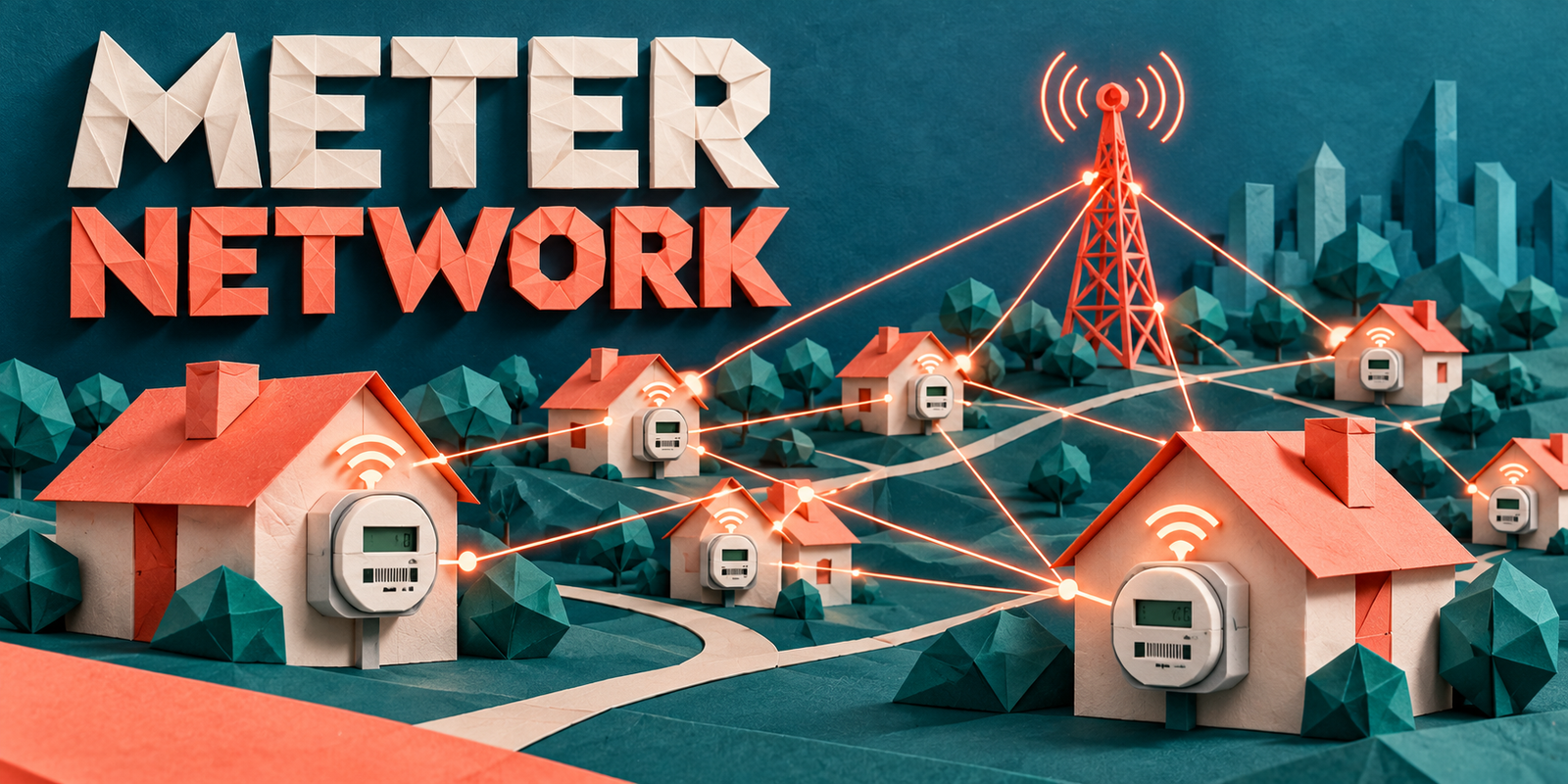
A smart meter network is the communication infrastructure that carries data between smart meters at customer premises and a utility’s head-end and data systems. Smart meters measure consumption, events and device status, but they cannot deliver that information on their own. The network moves it across an access network, sometimes a gateway or data concentrator, and a backhaul connection to the head-end system (HES), which passes it on to the meter data management system (MDMS) and utility applications.
Three terms are easily confused. A smart meter is the field device. A smart meter network is the connectivity layer that links meters to the utility. Advanced metering infrastructure (AMI) is the complete ecosystem of meters, communication, HES, MDMS and applications, explained in advanced metering infrastructure. This article goes deeper into the connectivity layer, because network reliability largely determines whether meter data arrives complete and on time, and network design is a critical part of any AMI deployment.
- Connectivity: A smart meter network connects field meters with utility systems.
- Layers: The network may contain access, aggregation and backhaul layers.
- Technology choice: Different utilities use different communication technologies, and none is universally best.
- Performance: Reliability, coverage and scalability are critical design goals.
- HES dependence: The HES can only manage meters it can reach through effective communication.
- Data availability: Network performance directly affects the completeness and timeliness of meter data.
- Security: Cybersecurity must be considered across the entire network, from meter to utility systems.
What Is a Smart Meter Network?
A smart meter network is the set of communication links, devices and protocols that transfer meter data and commands between smart meters in the field and the utility’s head-end system.
In simple terms, the smart meter is the field device, the smart meter network is the connectivity layer, and AMI is the complete metering, communication and data management ecosystem. The network is also called a smart metering network, an AMI communication network or a meter communication network.
| Component | Primary Role |
|---|---|
| Smart meter | Measures consumption and events at the premises, stores data and transmits it |
| Smart meter network | Carries data and commands between meters and the utility through access, aggregation and backhaul links |
| HES | Communicates with meters over the network and collects reads, events and status |
| MDMS | Validates, stores and manages meter data |
| Utility application | Uses managed data for billing, outage response, planning and customer services |
Each component depends on the one before it. A meter with no network cannot report, an HES with no network cannot reach meters, and an MDMS can only manage data that arrives. For the wider device picture, see key components of a smart grid.
Smart Meter Network Architecture
The conceptual path of meter data can be summarized as one chain.
Customer premises → Smart meter → Access (neighborhood) network → Gateway or data concentrator, where used → Backhaul network → Head-end system → MDMS → Utility applications
The meter at the premises generates the data. The access network connects it to a nearby point, which may be another meter, a collector or a cellular tower. A gateway or data concentrator, where the design includes one, gathers traffic from many meters. Backhaul carries the combined traffic to the utility, and the HES, MDMS and applications turn it into usable information.
Not every AMI architecture contains a separate data concentrator. Some meters connect directly to a cellular network, while others rely on collectors or concentrators. Architectures vary by utility, geography, communication technology, vendor and network design, so this chain is a model rather than a template.
Communication Layers in a Smart Meter Network
It helps to think of the network in five functional layers. These are practical groupings, not the formal layers of a networking model, and vendors draw the boundaries differently.
| Layer | Main Function | Example Technologies |
|---|---|---|
| 1. Meter / field layer | Measures, stores, formats and transmits data; executes supported commands | Smart meters with embedded communication modules |
| 2. Access / neighborhood network | Connects groups of meters to a nearby collection point or network | RF mesh, PLC, direct cellular, short-range radio |
| 3. Aggregation / gateway layer | Collects, forwards and sometimes pre-processes traffic from many meters | Data concentrators, collectors, cellular gateways |
| 4. Backhaul network | Carries aggregated traffic to the utility | Fiber, cellular, Ethernet, microwave, private networks |
| 5. Utility / head-end layer | Manages meter communication and delivers data to utility systems | HES, network management tools, integration middleware |
Layer 3 is optional in some designs. The key point is that a failure in any layer can interrupt data from every meter that depends on it.
Smart Meter Access Networks
The access network is how meters reach the nearby communication infrastructure. The main options are RF mesh, cellular and power line communication (PLC), sometimes supported by short-range links used for local functions such as commissioning or in-premises communication.
Several factors shape access network performance:
- Coverage: Whether every meter can reach the network, including basements, meter rooms and rural sites.
- Device density: Dense areas may help some topologies and strain others.
- Signal quality: Radio conditions or electrical noise affect message success.
- Topology: Mesh, star and hybrid arrangements behave differently when links fail.
- Communication reliability: Consistent delivery matters more than peak speed.
No access technology is universally better. The right choice depends on terrain, building types, meter density, existing infrastructure and the data the utility needs.
RF Mesh for Smart Meters
In an RF mesh, meters act as radio nodes that communicate with nearby meters and pass messages along until they reach a collection point such as a collector, access point or router. Messages can take several hops, and routing protocols select paths based on link quality. Where supported, the mesh is self-forming, so new meters join automatically, and self-healing, so traffic reroutes around a failed node or blocked link.
Advantages can include:
- Coverage extended through multiple nodes rather than only direct reach
- Good fit for dense meter deployments
- Multiple communication paths between a meter and the collection point
Considerations include radio interference, the physical environment such as terrain, foliage and building materials, careful network planning, device density and routing performance. Too many hops can add delay, and too many nodes sharing a collector can create congestion. Implementations differ between vendors and standards, so these points describe general behavior rather than every RF mesh product.
Cellular Smart Meter Networks
Cellular connectivity uses mobile networks for AMI communication. Meters may contain a cellular module and connect directly, or they may connect to a cellular gateway that serves a group of meters over another access technology. The underlying network may be a public mobile network or, where a utility operates one, a private cellular network. Low-power cellular IoT technologies are used for some metering where available.
Points to weigh:
- Coverage: Useful where mobile coverage exists, including some rural and remote areas, but indoor and underground meter locations can be difficult.
- Deployment simplicity: Direct connection can avoid building a dedicated field network.
- Network dependency: Performance depends on a network the utility may not control.
- Recurring connectivity considerations: Service arrangements and ongoing connectivity costs need evaluation.
- Availability: Congestion or outages on the mobile network can affect meter communication.
The same cellular technology and coverage are not available everywhere, so utilities should verify local conditions and the planned lifetime of the technology.
PLC and Other Communication Options
Power line communication (PLC) sends data over existing electrical conductors, so no separate communication path is needed to the meter. In AMI, narrowband PLC is common, and standards such as G3-PLC and PRIME are used in some deployments. Because signals generally do not pass freely through distribution transformers, a data concentrator at the substation or transformer often collects meter traffic on the low-voltage network.
PLC challenges include electrical noise from connected equipment, signal attenuation, network topology and the condition of the low-voltage network. Results depend heavily on local deployment conditions, so field testing matters.
Other options appear mainly in the aggregation and backhaul layers:
- Fiber and Ethernet: High-capacity wired links to substations and offices.
- Microwave: Point-to-point wireless links where fiber is impractical.
- Private utility networks: Utility-controlled radio or fiber networks.
- Specialized technologies: Satellite or other links for isolated sites.
For the broader communication landscape, see smart grid communication networks.
Backhaul Networks in AMI
Backhaul carries aggregated meter data from the field network to the utility. A typical path is: meter, access network, gateway, backhaul, HES. Options include fiber, cellular, Ethernet, microwave, private networks and other utility communication infrastructure.
Backhaul performance matters because it is shared. One failed meter affects one customer, but a failed backhaul link can silence an entire area. Key considerations are:
- Bandwidth: Enough capacity for the combined traffic, including peaks after outages.
- Reliability: Stable links with predictable behavior.
- Latency: Delay that suits the applications being supported.
- Availability: Uptime and recovery behavior, including during storms.
- Redundancy: Alternative paths for critical aggregation points.
Gateways and Data Concentrators
Gateways, collectors and data concentrators sit between the access network and backhaul where the architecture uses them. Their functions may include:
- Aggregating communication from many meters
- Handling protocols, translating between access-network and backhaul formats
- Forwarding data and commands
- Local processing, such as scheduling or storing data, where supported
- Network management tasks such as device registration and diagnostics
- Communication optimization to reduce traffic and retries
Not every smart meter architecture requires a separate gateway or concentrator. Meters with direct cellular connections may bypass this layer entirely. Where concentrators are used, they become important points of failure and security, so their placement, power backup and monitoring need careful design.
Smart Meter Network and HES
The HES is where the network meets utility software. The flow is: smart meter, communication network, gateway where applicable, backhaul, HES. Network communication moves the messages. HES application functions decide what to ask meters and what to do with the replies.
After receiving communication, the HES typically handles:
- Meter reads: Scheduled and on-demand readings.
- Events: Alarms such as power loss or tamper indications.
- Device status: Meter health and configuration information.
- Communication status: Which meters are reachable and when they last reported.
- Commands, where supported: For example remote configuration or connect and disconnect operations.
The HES typically uses meter-level protocols, such as DLMS/COSEM or the ANSI C12 series, to interact with meters, then passes validated communication results to the MDMS. See advanced metering infrastructure for the full ecosystem.
Smart Meter Data Flow
Forward path: meter to utility
The meter measures electricity
Consumption and other values are recorded at set intervals.
The meter stores data
Data is held locally until it can be sent.
The network establishes communication
The meter joins or contacts its access network.
Data moves through the access layer
Messages travel directly or through other nodes.
A gateway forwards data, where applicable
Traffic is aggregated and passed on.
Backhaul delivers the information
Data reaches the utility’s network.
The HES receives it
Reads, events and status are collected.
The MDMS processes meter data
Data is validated, estimated where needed, and stored.
A utility application uses the data
Billing, outage management and planning draw on it.
Reverse path: utility to meter
Where two-way communication is supported, commands and requests travel the opposite way: an application or operator request reaches the HES, which sends it through backhaul, any gateway and the access network to the meter. The meter acts and returns a confirmation along the same path. Reverse traffic needs stronger authentication because it can change meter behavior. For the wider workflow, see how smart grid technology works.
Smart Meter Network Reliability
Reliability does not simply mean the meter is online. A meter can appear connected yet deliver incomplete, delayed or duplicated data. In this context reliability covers successful communication, availability, coverage, redundancy, fault tolerance, network monitoring, recovery after outages and device availability.
| Reliability Factor | Why It Matters |
|---|---|
| Successful communication | Reads and events must actually reach the HES, not merely be sent |
| Availability | Network components must be working when data is due |
| Coverage | Meters outside coverage create missing data |
| Redundancy | Alternative paths limit the effect of a single failure |
| Fault tolerance | The network keeps working despite failed nodes or links |
| Monitoring | Problems are found before customers or billing are affected |
| Recovery after outages | Meters reconnect and backlogged data is delivered without overload |
| Device availability | Meter hardware and modules must remain healthy over long lifetimes |
Latency, Bandwidth and Data Volume
Latency is the delay between sending and receiving a message. Bandwidth is the capacity available to carry data. Data volume is how much data the system generates. Availability is the proportion of time the path works. Different AMI applications place different demands on each.
| Application | Communication Character |
|---|---|
| Periodic meter reading | Scheduled, moderate volume, usually tolerant of delay |
| Event reporting | Small, irregular messages where timeliness matters more |
| Two-way commands | Needs reliable, authenticated delivery and confirmation |
| Near-real-time applications | More frequent data, lower delay and steadier availability |
There are no universal latency requirements. Architecture and application determine what is needed, and some networks suit periodic reading better than frequent or near-real-time use. See real-time grid data for how timing affects utility decisions.
Smart Meter Network Scalability
A network grows from a pilot, to thousands of meters, to a large-scale deployment, and its needs change at each step. Planning should address:
- Device density: More nodes sharing links or collectors.
- Addressing: Unique identities and registration for every meter.
- Network management: Tools to configure and diagnose very many devices.
- Traffic and data volume: Higher message counts, especially after outages.
- Monitoring: Automated alerts instead of manual checks.
- Firmware and device management: Orderly, staged updates.
- Capacity planning: Headroom in access, gateway and backhaul layers.
A network that works for a small pilot may need a different architecture and operational processes at production scale. Pilots rarely reveal congestion or management limits that appear later.
Network Redundancy and Resilience
Resilience is the ability to keep delivering data, or recover quickly, when something fails. Common concepts include:
- Multiple communication paths: Meters or gateways that can reach more than one next hop.
- Redundant backhaul: A second link for important aggregation points.
- Failover: Automatic switching to a backup path.
- Network recovery: Orderly restoration after widespread outages.
- Device reconnection: Meters rejoining without manual intervention.
- Distributed routing: Routing decisions spread across nodes rather than a single controller.
This matters because meter communication supports billing and, increasingly, outage and operational use. The network may need to work hardest when the grid is under stress, so backup power and recovery behavior deserve attention.
Network Monitoring and Management
Utilities need visibility into the network itself, not only the data it carries. Useful monitoring covers:
- Device connectivity and last-contact times
- Communication failures and retry patterns
- Signal quality, where measurable
- Network availability
- Message delivery success
- Gateway status
- Backhaul status
- Alarms and events from network devices
Monitoring should be part of AMI operations, with clear ownership and response procedures. Without it, communication gaps are often found only when reads go missing or billing is affected.
Smart Meter Network and MDMS
The roles are distinct. The network moves information. The HES communicates with meters. The MDMS manages meter data, including validation, estimation and editing, storage and delivery to other systems. Utility applications use the managed data.
The MDMS does not replace the network. It depends on the network and HES for incoming data, and its data quality checks can reveal network problems through patterns of missing or late intervals. The reverse is also true: a perfect network cannot compensate for poor data management downstream.
Smart Meter Network Cybersecurity
Security must cover the whole path: meter, network, gateway, backhaul, HES and utility systems. A weakness at any point can affect the rest. Defensive priorities include:
- Meter authentication and device identity: Each device proves who it is before joining.
- Access control: Role-based limits on who can read, configure or command meters.
- Encryption and secure communication: Protecting data in transit across each link.
- Key and certificate management: Secure creation, distribution, rotation and revocation, where used.
- Network segmentation: Separating AMI networks from corporate and operational systems.
- Gateway and HES security: Hardening and patching the aggregation points and head-end.
- Firmware management: Signed, tested, staged updates.
- Monitoring, logging and incident response: Detecting unusual behavior and responding with practiced procedures.
- Vendor security: Assessing supplier practices and support lifetimes.
Meters stay in service for many years, so security design must anticipate long lifecycles and updates. For the broader context, see smart grid challenges.
Common Smart Meter Network Challenges
| Challenge | Possible Impact | Practical Mitigation |
|---|---|---|
| Poor coverage | Meters that cannot report | Site surveys, additional nodes or an alternative technology |
| Communication interference | Lost or repeated messages | Spectrum planning, field testing |
| Remote locations | Isolated meters with weak links | Cellular, satellite or other fit-for-purpose links |
| Network congestion | Delays and failed reads | Capacity planning, traffic scheduling |
| Device failures | Missing data from affected meters | Health monitoring, replacement processes |
| Power outages | Loss of network nodes and gaps in data | Backup power, outage-aware design |
| Backhaul failures | Whole areas going silent | Redundant paths, monitoring |
| Legacy integration | Data silos, manual workarounds | Gateways, middleware, phased replacement |
| Vendor interoperability | Lock-in, costly integration | Standards-based interfaces, integration testing |
| Scalability | Performance falls as meters are added | Staged rollout, scale testing |
| Cybersecurity | Risk to data and operations | Layered defenses, monitoring |
| Device lifecycle management | Outdated or unsupported devices | Lifecycle planning, firmware management |
| Data synchronization | Inconsistent records between systems | Time synchronization, reconciliation checks |
Traditional Meter Communication vs Smart Meter Network
Traditional metering is not obsolete. Many utilities still operate electromechanical and early electronic meters successfully, and the comparison shows where a network adds capability.
| Aspect | Traditional Metering | Smart Meter Network |
|---|---|---|
| Meter reading | Manual or periodic drive-by reading | Automated, remote collection |
| Communication | Limited or none | Dedicated network layers |
| Data frequency | Often monthly or periodic | Interval data, depending on design |
| Remote access | Site visits needed | Possible through the HES |
| Network visibility | Not applicable | Connectivity and health can be monitored |
| Events | Discovered during visits or customer calls | Reported by meters where supported |
| Two-way communication | Generally absent | Supported in many designs |
| Scalability | Scales with field staff | Scales with network design and management |
| Monitoring | Periodic checks | Ongoing monitoring tools |
| Utility integration | Manual or batch | Integrated through HES and MDMS |
| Maintenance | Mechanical testing and replacement | Adds firmware, network and device management |
Smart Meter Network Technology Comparison
The table uses qualitative descriptions only. Actual performance depends on the product, standard, spectrum, environment and design.
| Technology | Typical AMI Use | Coverage | Key Strength | Main Consideration |
|---|---|---|---|---|
| RF mesh | Access network between meters and collection points | Extended through multi-hop nodes | Multiple paths and flexibility in dense areas | Planning, interference and routing behavior |
| Cellular | Direct meter links or gateway backhaul | Depends on mobile network footprint | Simple deployment where coverage exists | Dependence on carrier network and service terms |
| PLC | Low-voltage access to a concentrator | Follows the electrical network | Uses existing conductors | Noise and topology sensitivity |
| Fiber / Ethernet | Backhaul and aggregation sites | Where cable is installed | High capacity and stable links | Installation effort and cost |
| Private utility networks | Access or backhaul under utility control | Designed to the utility’s footprint | Control over performance and security | Build, spectrum and operating responsibility |
How Should Utilities Select a Smart Meter Network?
Selection should begin with utility requirements, not the popularity of a technology. The following factors form a practical framework.
| Factor | Question to Ask |
|---|---|
| 1. Meter density | How many meters per area, and how are they spread? |
| 2. Geographic coverage | What terrain and service area must be covered? |
| 3. Urban vs rural | Do different areas need different approaches? |
| 4. Existing infrastructure | What fiber, towers, poles and networks can be reused? |
| 5. Communication reliability | What level of delivery success does the business need? |
| 6. Data requirements | What interval, event and command traffic is expected? |
| 7. Scalability | Can the design grow without redesign? |
| 8. Cybersecurity | Which security capabilities are built in and verified? |
| 9. Lifecycle costs | What are installation, operating and replacement costs over time? |
| 10. Vendor interoperability | Are interfaces open and testable? |
| 11. Maintenance | What field and network support will be required? |
| 12. Regulatory requirements | Which rules affect technology, data and spectrum? |
| 13. Backhaul availability | Is suitable, redundant backhaul accessible? |
Many utilities combine technologies, for example mesh in dense areas and cellular in remote ones, managed through a common HES.
Illustrative Example: A Mixed Urban and Semi-Rural Deployment
Illustrative Example — not a real utility project or case study.
A utility deploys smart meters across a mixed urban and semi-rural service area. The sequence might look like this:
Meters collect interval data
Each meter records and stores readings.
Urban meters use a suitable access-network architecture
For example, a mesh with collection points in dense areas.
Remote meters use another connectivity option
For example, cellular where mesh coverage would be sparse.
Gateway and backhaul infrastructure aggregates data
Where applicable, traffic is combined and carried to the utility.
The HES receives meter communication
Reads, events and communication status arrive.
The MDMS manages validated meter data
Data is checked and made available to applications.
Network monitoring identifies communication gaps
Meters with repeated missing reads are flagged.
Utility teams investigate persistent issues
They check coverage, device health and backhaul status.
Network performance improves as deployment scales
Additional nodes, adjusted settings or alternative links address recurring gaps.
Smart Meter Network Deployment Roadmap
Assess existing infrastructure
Inventory towers, fiber, poles, substations and current meters.
Map meter locations and density
Identify clusters, gaps and difficult sites.
Define communication requirements
Set data, timing and reliability needs.
Evaluate technology options
Compare against requirements and local conditions.
Design access and backhaul architecture
Decide on layers, gateways and redundancy.
Define cybersecurity
Plan identity, encryption, segmentation and monitoring.
Pilot selected areas
Test in representative urban, rural and difficult locations.
Measure network performance
Track delivery success, coverage and recovery behavior.
Integrate with HES and MDMS
Confirm data and commands flow end to end.
Train operations teams
Prepare staff for network monitoring and troubleshooting.
Scale gradually
Expand in phases and adjust processes.
Monitor lifecycle performance
Track degradation, firmware needs and replacement planning.
At a high level, troubleshooting follows the same layers: confirm the meter is healthy, check the access link, check the gateway, check backhaul, then check the HES. Working from the field upward isolates where messages stop.
Future of Smart Meter Networks
These are trends and possibilities, not guarantees. Some are emerging and others are already deployed in some utilities, so adoption varies.
- More reliable connectivity and greater network automation, including self-optimizing behavior
- Edge processing in meters and gateways to filter and analyze data locally
- Improved device management and stronger cybersecurity practices
- More granular meter data supporting advanced analytics
- Better integration with DERs and EV charging visibility
- Advanced demand response that depends on dependable two-way communication
- More interoperable communication architectures built on shared standards
For the longer view, see the electric grid in 2035.
Conclusion
Smart meters need reliable communication networks to be useful. A smart meter network is the connectivity layer within AMI: access networks connect field meters, gateways or concentrators may aggregate communications, and backhaul connects the field network to utility systems. The HES manages meter communication, and the MDMS manages meter data.
Reliability, scalability and cybersecurity are critical across every layer, and no single technology suits every utility. Network architecture should be selected from utility requirements, tested in pilots and monitored throughout its lifecycle. To see the complete ecosystem, read advanced metering infrastructure.
Frequently Asked Questions About Smart Meter Networks
What is a smart meter network?
A smart meter network is the communication infrastructure that carries data between smart meters and utility systems. It may include access networks, gateways or data concentrators, and backhaul links.
It is the connectivity layer within advanced metering infrastructure (AMI).
How does a smart meter network work?
Meters record data and send it over an access network, directly or through nearby nodes. A gateway may aggregate the traffic, and backhaul carries it to the head-end system.
The HES collects the data and passes it to the MDMS. Where supported, commands travel the reverse path.
Why is a smart meter network important?
Without a network, smart meters cannot send data or receive commands. Network quality determines how complete and timely meter data is.
It therefore affects billing, outage awareness, planning and other AMI applications.
What are the main components of a smart meter network?
The main components are:
- Smart meters with communication modules
- Access network links such as RF mesh, cellular or PLC
- Gateways or data concentrators, where used
- Backhaul links such as fiber, cellular or microwave
- The HES and network management tools
What are the challenges of a smart meter network?
Common challenges include coverage gaps, interference, congestion, backhaul failures, outages, interoperability, scalability and cybersecurity.
Utilities respond with site surveys, redundancy, monitoring, standards-based interfaces and phased deployment.
Where are smart meter networks used?
They are used by electric utilities for residential, commercial and industrial metering, and similar networks support some water and gas metering.
Applications include remote reading, outage detection, load analysis and customer services.
What is the difference between RF mesh and cellular smart meter networks?
RF mesh uses meters as radio nodes that relay messages to a collection point, typically on a utility-managed network. Cellular connects meters or gateways to a mobile network operated by a carrier or utility.
Each has different coverage, control and cost trade-offs, and neither is universally better.
How does a smart meter network connect to HES and MDMS?
The network delivers meter communication to the HES through backhaul. The HES collects reads, events and status, and sends commands where supported.
It then passes the data to the MDMS, which validates and manages it for utility applications.

I share real stories, practical ideas and honest perspectives on business, marketing and life. This blog is a space to learn, grow and connect.