
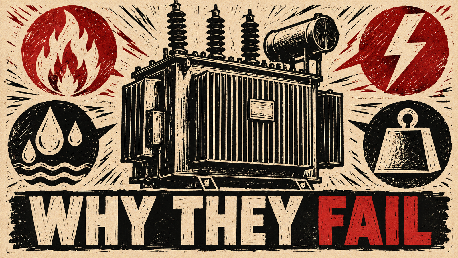
Energy Infrastructure · Transformers & Grid Assets
Transformer failures rarely have a single cause. This guide explains the electrical, thermal, mechanical, insulation, environmental and operational mechanisms behind them, and how engineers assess and manage the risk.
Transformers are among the most critical and costly assets in a power network, so understanding transformer failure causes is central to reliability planning. A failure rarely starts with one dramatic event. More often, stresses accumulate over years until a weakened component can no longer cope.
This guide explains how failures develop, what each group of causes looks like, which warning signs and diagnostic methods help, and how utilities manage risk. It does not quote failure statistics or universal limits. Thresholds and intervals depend on the equipment design, manufacturer guidance and applicable standards.
Introduction: Why Understanding Transformer Failure Causes Matters
A failed transformer can interrupt supply, damage nearby equipment, create fire or environmental risk and take a long time to replace. Knowing the transformer failure causes behind an event lets teams repair the right thing, protect similar units and improve planning. For a wider view of how equipment faults fit into outages, see our guide to what causes power grid failures.
What Are Transformer Failures?
A transformer failure is the loss of the ability to perform a required function within acceptable limits. It can be sudden, such as an internal fault that trips protection, or gradual, such as slow insulation deterioration that makes continued service unacceptable. Some failures are catastrophic. Others are functional, for example a unit that must be removed because its condition can no longer be trusted.
It helps to separate three ideas. The initiating event starts the sequence, the contributing conditions make damage more likely or more severe, and the resulting damage is what inspection finds. A burnt winding may be the damage, while the initiating event was a surge and the contributing condition was weakened insulation.
How Transformer Failures Develop
Most failures follow a progression. A stress, such as heat, moisture, voltage or force, degrades a material. The degradation reduces strength margins. A later event, such as a fault, a surge or a heavy load, then exceeds the remaining margin.
Stresses interact. Moisture lowers dielectric strength, heat accelerates ageing and releases more moisture, and aged insulation is less able to withstand a fault force or a surge. This is why a single trigger often looks sudden while the underlying cause was long-running.
Because of this, root-cause analysis should look beyond the failed component. It should ask what changed in loading, environment, maintenance and protection operations before the event.
Major Categories of Transformer Failure Causes
Causes can be grouped into electrical, thermal, mechanical, insulation and oil-related, environmental, operational, and manufacturing, design or installation factors. The groups overlap, so Table 1 is a guide rather than a strict classification.
Table 1: Transformer Failure Cause Categories
| Cause Category | Typical Mechanisms | Possible Consequences | Relevant Assessment Methods |
|---|---|---|---|
| Electrical | Through-faults, surges, partial discharge, insulation breakdown, connection faults | Winding damage, flashover, internal arcing, protection operation | Electrical tests, partial discharge assessment, protection-event review |
| Thermal | Overloading, cooling problems, hot spots, high ambient temperature | Accelerated insulation ageing, gas generation, reduced life | Temperature trends, loading review, thermal imaging, oil analysis |
| Mechanical | Short-circuit forces, vibration, loose parts, transport damage | Winding deformation, clamping loss, later electrical failure | Frequency response and impedance tests, vibration or acoustic checks |
| Insulation and oil | Moisture, contamination, oxidation, leaks | Reduced dielectric strength, sludge, reduced cooling | Oil testing, dissolved gas analysis, dielectric response tests |
| Environmental | Lightning, flooding, contamination, corrosion, fire, wildlife | Flashovers, leaks, external damage, enclosure deterioration | Visual inspection, bushing checks, site risk review |
| Operational and maintenance | Repeated overloads, poor load management, wrong settings, missed maintenance | Cumulative degradation, undetected defects | Records review, loading analysis, maintenance audit |
| Manufacturing, design, installation | Material or workmanship defects, design margins, commissioning errors | Early-life failures, unexpected weakness | Factory and site test records, commissioning review |
Electrical Causes of Transformer Failures
Short circuits and through-fault stresses
A through-fault is a fault elsewhere in the network that passes current through the transformer. It can impose significant mechanical and thermal stress even when protection operates correctly, and repeated events may cause cumulative damage.
Insulation breakdown
Insulation can fail when electrical stress exceeds its strength. Typical contributors are ageing, moisture, contamination, voids and earlier damage from surges or partial discharge.
Overvoltage and lightning-related surges
Lightning and switching surges produce fast, high voltage stresses, often concentrated on the first turns of a winding. Surge arresters, insulation coordination and good grounding reduce risk but cannot remove it.
Partial discharge and electrical discharge activity
Partial discharge is a localized discharge that does not completely bridge the insulation. It may start at voids, sharp edges or contamination and can erode insulation over time. It is both a symptom and a cause of deterioration.
Winding faults and electrical connections
Turn-to-turn and winding-to-winding faults often follow insulation weakening. Poor connections, including leads, joints and tap changer contacts, can overheat and degrade the oil or insulation around them.
Thermal Causes of Transformer Failures
Overloading and excessive operating temperature
Overloading may raise winding temperature and accelerate insulation ageing. The actual effect depends on loading duration, cooling, ambient conditions and equipment design, so loading guidance from the manufacturer and applicable standards should be used.
Cooling-system problems
Failed fans or pumps, blocked radiators, restricted airflow and poor oil circulation reduce heat removal. A transformer can run hot at modest load when cooling is impaired.
Hot spots and uneven temperature distribution
Temperature is not uniform. The hottest point in a winding, or at a poor connection or stray-flux region, can be well above bulk oil temperature, so surface or oil readings may understate local stress.
Insulation ageing and thermal deterioration
Paper insulation weakens with time at temperature, and moisture and oxygen can speed this up. Ageing is gradual and non-linear, and it reduces the ability to survive mechanical and electrical events.
High ambient temperatures and ventilation issues
High ambient temperature, direct sun and poor ventilation in rooms or enclosures reduce the margin available for load. Dry-type units in enclosed spaces are particularly dependent on airflow.
Mechanical Causes of Transformer Failures
Winding deformation and movement
Windings can shift, tilt or buckle after high forces. Deformation may not cause an immediate failure but can reduce clearances and weaken the unit for the next event.
Vibration and mechanical stress
Normal operation produces some vibration and hum. Excessive or changing vibration may point to looseness, clamping problems or resonance, though other explanations are possible.
Damage from short-circuit forces
Short-circuit forces rise sharply with current, and design determines how well windings withstand them. Clamping condition and ageing of supporting materials affect the remaining margin.
Loose connections and component deterioration
Vibration, thermal cycling and ageing can loosen connections and gaskets or degrade supports. Loose joints heat locally and can lead to arcing.
Transport, handling and installation damage
Impacts, poor lifting or inadequate securing can displace internal parts or damage bushings. Such damage may remain hidden until the unit is stressed in service, so impact records and acceptance tests matter.
Insulation and Oil-Related Causes
Moisture ingress
Moisture can enter through breathers, gaskets and poor sealing, and ageing paper also releases water. It lowers dielectric strength, and its distribution between paper and oil changes with temperature.
Insulation contamination and deterioration
Particles, dissolved by-products and conductive deposits can reduce insulation performance and encourage discharge. Contamination may come from manufacture, maintenance or ageing.
Oil leakage and oil-quality changes
Leaks lower oil level and can expose parts and reduce cooling. Oil quality also changes with service, which may affect dielectric and cooling performance. Environmental duties apply to leaks.
Oxidation and sludge formation, where applicable
In oil-filled units, oxidation can form acids and sludge that may impair heat transfer and attack insulation. How quickly this occurs depends on oil type, temperature and sealing arrangement.
Gas generation and diagnostic limitations
Faults and ageing generate gases that dissolve in oil, which is why dissolved gas analysis supports diagnosis in applicable oil-filled equipment. Gas patterns need qualified interpretation using standards such as IEC 60599 and IEEE C57.104 (check the current editions), and should not be treated as proof of a single fault. Sampling errors, earlier events and tap changer leakage can also affect results.
Environmental Causes of Transformer Failures
Lightning, storms and flooding
Lightning can cause surges and flashovers. Storms can damage connections and structures, and flooding can reach terminals, cooling gear and control cabinets.
Dust, humidity and contamination
Dust, salt and industrial deposits on bushings and insulators can cause surface tracking and flashover, especially in humid conditions. Dry-type windings are also sensitive to dust and condensation.
Corrosion and aggressive environments
Coastal, chemical and humid sites accelerate corrosion of tanks, fittings and enclosures. Corrosion can eventually compromise seals and allow leaks or moisture ingress.
Fire exposure and external physical damage
Nearby fires, wildfire smoke, vehicle impacts and vandalism can damage a transformer. Transformers themselves can also be a fire source, so separation and containment are part of site design.
Wildlife and other external interference
Birds, squirrels and other animals can bridge exposed terminals and cause faults at overhead and open-air installations. Guarding and enclosure design reduce this risk.
Operational and Maintenance-Related Causes
Repeated overloads
Occasional peaks may be acceptable within loading guidance, but frequent or prolonged overload consumes insulation life faster, particularly when cooling or ambient conditions are poor.
Poor load management
Unbalanced phases, harmonic-rich loads, new EV or heat pump demand and reverse power flow from distributed generation can change loading in ways the original design did not assume.
Incorrect operation or unsuitable settings
Wrong tap settings, protection settings that do not match the transformer, disabled cooling controls and bypassed alarms can turn a manageable condition into damage.
Inadequate inspection and maintenance
Missed inspections allow small leaks, loose connections and blocked cooling to become larger problems. Records gaps also make later root-cause analysis harder.
Ageing equipment and unavailable spare parts
Older units may have limited condition history, obsolete components and longer repair times. Without spares or replacement plans, a minor defect can become a long outage.
Manufacturing, Design and Installation Factors
Some failures trace back to the unit itself. Design margins may be inadequate for the actual duty, materials may contain defects, and workmanship issues such as poor drying, contamination or weak joints can remain hidden for years. Installation and commissioning errors, including wrong connections, poor grounding or damaged parts, can also create latent weakness.
Review of factory test reports, commissioning records and design duty assumptions helps determine whether a failure was linked to these factors. It does not prove one, because service conditions usually also contribute.
Common Transformer Warning Signs
A warning sign does not necessarily confirm a fault. Each indicator below can have several explanations and must be interpreted with operating history, design, loading, manufacturer guidance and applicable standards.
Table 2: Warning Signs and Possible Causes
| Warning Sign | Possible Explanations | Recommended Assessment | Important Limitations |
|---|---|---|---|
| Abnormal temperature trend | Higher load, cooling problem, hot connection, instrument error, ambient change | Compare with load and ambient trends; verify instruments; qualified inspection | Single readings can mislead; internal hot spots may not show |
| Unusual noise or vibration | Loose parts, core or clamping issues, load or voltage change, resonance | Compare with earlier baseline; vibration or acoustic assessment | Noise varies with load and voltage; origin may be unclear |
| Oil leak | Gasket ageing, corrosion, loose fittings, temperature cycling | Locate source; check oil level; plan repair | Small leaks may not signal internal faults, and absent leaks do not prove soundness |
| Gas-analysis change | Thermal or electrical activity, ageing, tap changer leakage, sampling issue | Review trend, repeat sampling if appropriate, qualified interpretation | Not proof of one fault; interpretation depends on equipment and history |
| Protection operation | Internal fault, external fault, inrush, setting or device problem | Review event records and fault data; decide on testing before re-energizing under procedure | The relay trip alone does not identify the cause |
| Bushing deterioration | Contamination, cracking, moisture, ageing, mechanical damage | Visual and electrical bushing assessment | Visual condition may not reflect internal state |
| Unexpected change in electrical measurements | Winding or core change, connection problem, measurement error | Repeat measurements and compare with baseline and factory data | Needs good reference data and test conditions |
Transformer Diagnostic and Condition Assessment Methods
No single method gives a complete picture. Qualified personnel should combine several sources of evidence, follow manufacturer instructions and use applicable standards for interpretation. All testing requires approved procedures and safe isolation.
Table 4: Diagnostic Methods
| Method | Purpose | Limitations |
|---|---|---|
| Visual inspection | Spot leaks, corrosion, damage, contamination and gauge readings | Reveals external condition only |
| Oil testing, where applicable | Assess moisture, dielectric and chemical condition of the oil | Sampling and handling affect results; limits depend on equipment class and guidance |
| Dissolved gas analysis | Detect gases that may indicate thermal, electrical or ageing activity | Needs qualified interpretation; not definitive for a single fault |
| Electrical testing | Check insulation, winding resistance, ratio, impedance and response | Offline tests need isolation; results need reference data |
| Thermal imaging | Find external hot spots such as connections and cooling issues | Surface view only; depends on load and conditions |
| Vibration or acoustic assessment | Identify unusual mechanical or discharge-related signals | Interpretation needs experience and baselines |
| Protection-event review | Understand what faults the transformer experienced | Depends on record quality and settings |
| Historical trend analysis | Reveal gradual change across tests, loading and events | Needs consistent, reliable records |
Any numeric acceptance or alarm limit should come from the relevant equipment standard or the manufacturer, and should be checked against the current edition. This article does not give universal limits.
How Transformer Failure Causes Differ by Transformer Type
The balance of causes shifts with design and duty. The table shows typical emphasis only.
| Transformer Type | Where Emphasis Often Lies |
|---|---|
| Oil-filled distribution | Overloading, moisture and sealing, surges, external damage, limited condition data |
| Dry-type and cast resin | Ventilation, dust and condensation, thermal limits, cracking of solid insulation |
| Substation power transformers | Through-faults, tap changer condition, insulation ageing, cooling systems |
| Generator or renewable step-up | Frequent switching, load cycling, harmonics from power electronics |
| Industrial and furnace | Severe duty cycles, harmonics, repeated fault and switching stresses |
Our guide to transmission and distribution networks explains why equipment duty differs across the grid.
Practical Illustrative Scenarios
These scenarios are illustrative, not real-world case studies. They show how evidence is combined, not how any specific unit behaved.
Scenario 1: Repeated high loading and abnormal temperature trends (illustrative)
Evidence: Load records show frequent peaks near or above rating, and temperature indicators trend upward over several seasons.
Plausible causes: Load growth, reduced cooling, higher ambient temperature or an instrument problem.
Next steps: Check the instrument, review load against manufacturer loading guidance, inspect cooling, and consider oil analysis if applicable. Plan load transfer or capacity reinforcement if needed.
Limitations: Without internal temperature data, the remaining insulation life cannot be judged from loading alone.
Scenario 2: Change in dissolved gas analysis results (illustrative)
Evidence: A routine oil sample on an oil-filled unit shows changes in dissolved gases compared with earlier samples.
Plausible causes: Thermal activity, electrical discharge, cellulose ageing, tap changer leakage or sampling and handling effects.
Next steps: Confirm with a repeat sample, review trend and load history, interpret using applicable standards and manufacturer advice, and consider electrical tests under safe isolation.
Limitations: Gas patterns are not definitive proof of one fault, and prior events or sampling errors can mislead.
Scenario 3: Protection operation after an external fault (illustrative)
Evidence: Protection operated after a fault on a downstream feeder, and the transformer was de-energized.
Plausible causes: Through-fault stress on the transformer, a protection event unrelated to damage, or a pre-existing weakness.
Next steps: Review fault current and duration records, inspect externally, and arrange qualified electrical tests, including winding-condition checks, before a decision under approved procedure. Compare with baseline data.
Limitations: Even if protection worked, mechanical damage may remain hidden, and tests need reference data.
Scenario 4: Corrosion, moisture ingress or deteriorating external components (illustrative)
Evidence: Inspection finds corrosion on the tank, weeping gaskets and a cracked bushing sealant.
Plausible causes: Coastal or humid environment, age, thermal cycling and deferred maintenance.
Next steps: Record and prioritize repairs, check oil level and moisture indicators where applicable, assess bushings, and review environmental protection.
Limitations: External condition does not prove internal damage, and a clean exterior does not prove soundness.
Preventive and Condition-Based Maintenance Strategies
Preventive work follows a schedule, while condition-based work responds to measured state. Most utilities combine both. Actual intervals depend on manufacturer instructions, applicable standards, utility policy and operating conditions. All work must be done by qualified personnel with approved procedures, appropriate isolation and applicable electrical safety requirements, and protection must never be bypassed.
Table 3: Failure Prevention and Maintenance Measures
| Risk or Failure Mechanism | Preventive or Monitoring Measure | What It Can Help Detect or Reduce | Limitations |
|---|---|---|---|
| Overloading | Loading review, temperature monitoring, capacity planning | Excessive loading and thermal stress | Depends on data quality and accurate rating information |
| Cooling problems | Inspection and function checks of cooling equipment | Blocked, failed or weak cooling | May not reveal internal flow problems |
| Moisture and oil condition | Sealing checks, oil testing where applicable | Moisture ingress, oil deterioration | Small sealed units may not allow sampling |
| Internal electrical activity | Dissolved gas analysis, partial discharge assessment | Early signs of thermal or electrical issues | Needs expert interpretation; not definitive |
| Surges | Surge arresters, grounding checks, insulation coordination | Reduced surge stress | Does not remove all surge risk |
| Through-fault damage | Fault-event records, post-event tests | Cumulative fault exposure and damage | Hidden damage may not be easily found |
| Loose connections | Thermal imaging, connection inspection | Hot or degraded joints | Needs load and safe access |
| Environmental exposure | Coatings, cleaning, drainage, wildlife guards, flood and fire planning | Contamination, corrosion and external interference | Local conditions can still overwhelm protection |
The Role of Sensors, AI and Predictive Maintenance
Sensors can track load, temperature, oil level and gas content, and some systems monitor bushings or discharge activity. They improve visibility but cannot prevent every failure. Our article on sensors and IoT devices in grid operations covers the wider data picture, and power system automation explains how monitoring links to control.
AI and machine learning can help identify anomalies and trends, as described in AI in smart grids. They cannot replace engineering judgment or guarantee failure prevention, and their output needs validation against inspection and test evidence.
Challenges in Transformer Failure Diagnosis
- Overlapping symptoms: different causes can produce the same indicator.
- Hidden damage: mechanical and internal insulation damage may not show externally.
- Missing baselines: without factory and early-life data, change is hard to judge.
- Data quality: inconsistent sampling, instrument drift and record gaps weaken analysis.
- Destroyed evidence: after a severe failure, the initiating event can be difficult to separate from consequential damage.
- Access limits: small sealed units may not support oil sampling or detailed testing.
Best Practices for Utility Asset Management
- Keep complete records of nameplate data, tests, loading, events and maintenance.
- Establish baselines at commissioning and compare later results with them.
- Match assessment depth to criticality and consequence of failure.
- Review fault-event exposure and follow up after severe through-faults.
- Use more than one evidence source before drawing conclusions.
- Take thresholds and intervals only from applicable standards, manufacturer guidance and utility policy.
- Use root-cause analysis that separates initiating event, contributing conditions and resulting damage.
- Plan spares and replacement before a unit reaches the point of unacceptable risk.
Key Takeaways
- Failures can come from one cause or from interacting electrical, thermal, mechanical, insulation, environmental and operational stresses.
- A warning sign does not necessarily confirm a fault.
- Overloading may accelerate ageing, but the effect depends on duration, cooling, ambient conditions and design.
- Through-faults can impose major stresses even when protection operates.
- Moisture, insulation condition and oil quality affect dielectric performance in oil-filled units.
- Dissolved gas analysis supports diagnosis but needs qualified interpretation.
- Monitoring and protection help detect problems but cannot prevent every failure.
- Root-cause analysis should separate initiating event, contributing conditions and resulting damage.
Conclusion
Transformer failures usually reflect stresses that built up over time and then met a triggering event. Understanding the main transformer failure causes helps engineers look past the visible damage to the conditions that allowed it.
Good records, sensible loading, protection, inspection and qualified testing reduce risk without removing it. Monitoring and analytics add value when they support, not replace, engineering judgment.
Frequently Asked Questions
What are the main causes of transformer failure?
Main causes include electrical stresses such as faults and surges, thermal stress from overloading or poor cooling, mechanical forces, moisture and oil problems, environmental exposure, operational and maintenance issues, and manufacturing or installation defects. Failures often involve several interacting causes.
How do electrical problems cause transformer failures?
Faults, surges and discharge activity can overstress or erode insulation, leading to winding faults or flashover. Through-faults can also damage windings mechanically even if protection operates.
How does overheating affect a transformer?
Higher temperature accelerates insulation ageing and may generate gases in oil-filled units. The actual effect depends on load duration, cooling, ambient conditions and design.
What warning signs may indicate transformer failure?
Possible signs include abnormal temperature trends, unusual noise or vibration, oil leaks, changes in gas analysis, protection operations, bushing deterioration and unexpected changes in electrical measurements. Each has several possible explanations and needs qualified assessment.
How can transformer failures be prevented or reduced?
Risk can be reduced through sound selection, load management, protection, inspection, condition-based maintenance and good records, following manufacturer guidance and applicable standards. No measure removes all risk.
How do utilities diagnose transformer failures?
They combine inspection, electrical and oil tests, dissolved gas analysis where applicable, protection-event review and trend analysis. Qualified personnel interpret the combined evidence rather than relying on a single indicator.
Have a question about power systems?
Questions about this topic or ideas for future articles? Get in touch.
Contact Us
I share real stories, practical ideas and honest perspectives on business, marketing and life. This blog is a space to learn, grow and connect.