Transmission and distribution are the two delivery stages of an electric grid. Transmission moves large amounts of power at high voltage over long distances, while distribution delivers that power at lower voltage to homes, businesses and industries. Understanding transmission vs distribution is a core part of electrical engineering and power systems work, because each network has its own voltage levels, equipment, losses and operating priorities.
Transmission moves electricity over long distances at high voltage. Distribution delivers electricity from substations to end users at lower voltages.
This guide compares both networks in practical detail. For a broader introduction, read our overview of electricity transmission and distribution first.
What Is the Difference Between Transmission and Distribution?
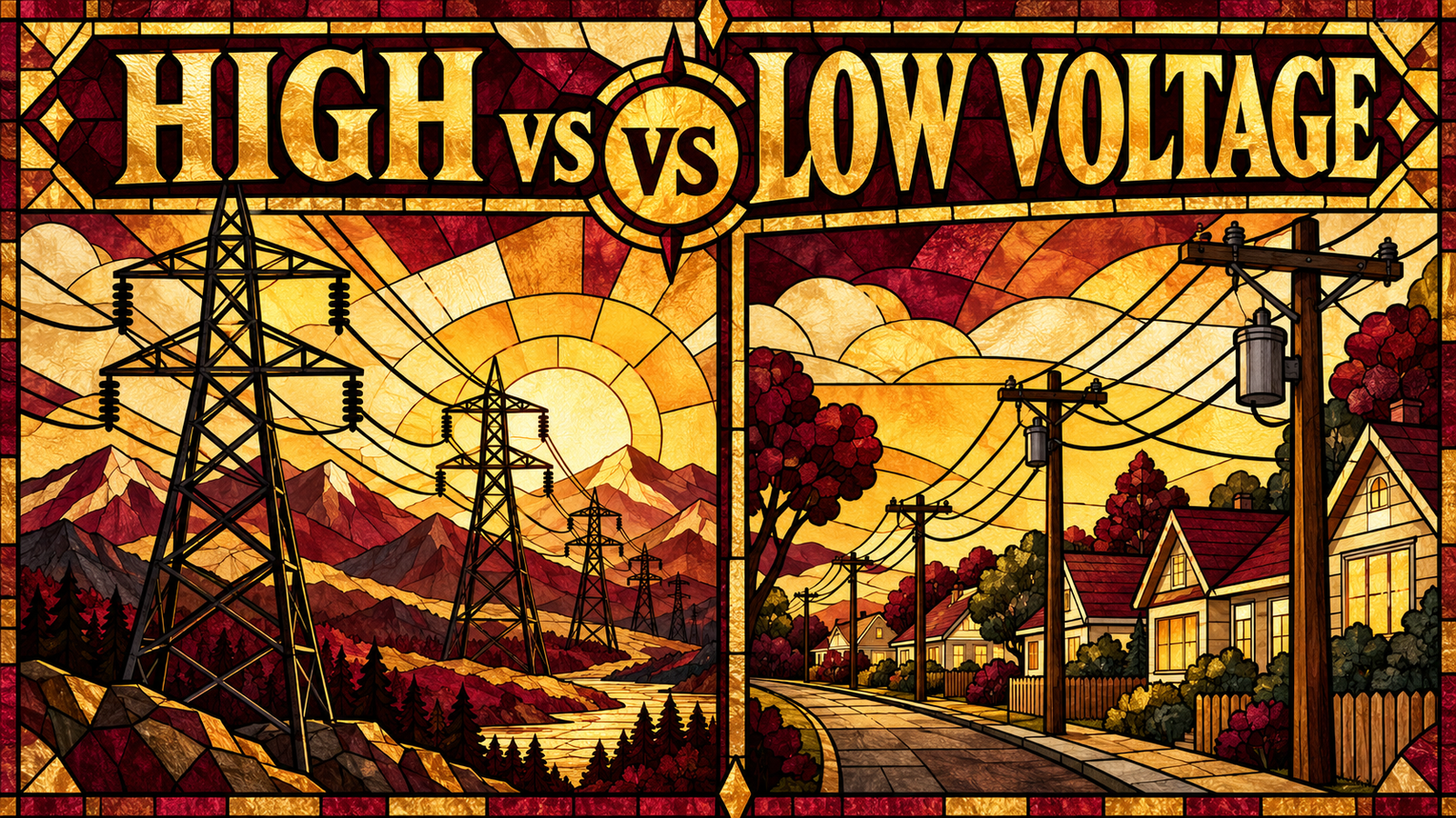
The difference is purpose and voltage. Transmission carries bulk power from power plants to major substations at high voltage, usually over long distances. Distribution takes power from those substations and delivers it to customers at medium and low voltage, usually over short distances.
A road analogy helps. Transmission lines are like highways that move large volumes quickly between cities. Distribution lines are like local streets that reach every address. Both are required, and a failure or limit in either one affects the customer.
Three practical differences stand out:
- Voltage: High or extra-high on transmission, medium and low on distribution.
- Structure: Transmission is usually meshed, with several paths. Distribution is usually radial, with one main path to each customer.
- Operation: Transmission operators balance the whole system. Distribution operators manage local feeders, voltage and restoration.
What Is Electrical Transmission?
Electrical transmission is the bulk transfer of electrical energy from generating stations to major load centers at high voltage.
Purpose and long-distance electricity transfer
Power plants are often far from large cities and industrial areas. The transmission system connects them, so power can flow from where it is produced to where it is needed. It also links regions and sometimes countries into an interconnected grid, which allows power sharing and mutual support.
Step-up transformation
Most generators produce power at a moderate voltage. A generator step-up transformer raises it to the transmission level. A higher voltage means a lower current for the same power, which reduces losses and lets each line carry more power.
Typical voltage ranges
Many systems treat lines of roughly 100 kV and above as transmission. Common classes include 110 kV, 132 kV, 220 kV and 400 kV, and some networks use 500 kV, 765 kV or higher. Voltage classes and the line between transmission and distribution vary by country and utility, so these figures are examples, not a universal standard.
Major transmission infrastructure
- Overhead lines on towers, and underground or subsea cables where needed
- Switching stations and transmission substations
- High-voltage direct current (HVDC) links for very long routes or for connecting separate grids
- Control centers that monitor and operate the network
Transmission substations
Transmission substations change voltage levels, switch circuits, house protection equipment and provide measurement points for operators. They are the nodes where lines meet and where power is routed toward load areas.
What Is Electrical Distribution?
Electrical distribution is the final stage of electricity delivery, carrying power from distribution substations to customers at medium and low voltage.
Purpose and distribution voltage levels
Distribution makes power usable and safe for customers. Medium-voltage (MV) circuits commonly operate between about 3 kV and 35 kV, with examples such as 11 kV, 13.8 kV and 33 kV. Low-voltage (LV) circuits, below about 1 kV, supply most customers, for example around 120/240 V or 230/400 V. Again, these differ between countries and utilities.
Distribution feeders and transformers
Feeders are medium-voltage circuits that leave a distribution substation and run through towns and neighbourhoods. Along the route, distribution transformers reduce the voltage to the level customers use. They can be mounted on poles, on pads or inside small enclosures.
Homes, commercial and industrial consumers
- Homes and small businesses: Supplied at low voltage through a service connection and meter.
- Commercial consumers: Larger buildings may take supply at medium voltage and use their own transformers.
- Industrial consumers: Factories often connect at medium voltage. The largest users may connect directly to sub-transmission or transmission.
Service connections
The service connection is the last link. It joins the network to the customer’s premises, usually through a service cable or overhead drop and a meter.
Transmission vs Distribution: Key Differences
The table compares typical characteristics. Values are general examples and differ between utilities.
| Feature | Transmission | Distribution |
|---|---|---|
| Main purpose | Bulk power transfer between generation and load centers | Final delivery to end customers |
| Typical voltage levels | High and extra-high voltage, commonly about 100 kV and above | Medium voltage (about 3–35 kV) and low voltage (below about 1 kV) |
| Distance | Tens to hundreds of kilometres, sometimes more | Typically a few to a few tens of kilometres per feeder |
| Customers served | Utilities, distribution networks and very large industrial users | Homes, businesses, commercial buildings and most industries |
| Equipment | Towers, high-voltage conductors, power transformers, high-voltage breakers and disconnectors, instrument transformers | Feeders, distribution transformers, reclosers, fuses, switchgear, service cables, meters |
| Network structure | Meshed, with multiple paths between points | Mostly radial, often with normally open tie points for backup |
| Energy losses | Lower per unit of power moved, because current is low | Often a larger share of total losses, because of lower voltage, branching and many transformers |
| Protection systems | Fast, selective schemes such as distance and differential protection | Overcurrent and earth-fault protection, fuses and reclosers, coordinated in sequence |
| Operational requirements | System-wide balancing, frequency and voltage control, stability and security | Feeder management, voltage regulation, fault isolation, restoration and DER integration |
| Reliability requirements | Very high, because a failure can affect a large area, so networks are planned to survive the loss of a single element | High, with outages usually local, and improved by backup feeders and automation |
Voltage Levels Explained
Voltage levels differ between countries, regions and utilities. The ranges below are typical examples, not a universal global standard. Always follow the standards of the system you work on.
Generation voltage
Large generators typically produce power at a moderate voltage, often in the range of about 6 kV to 25 kV, which is limited by insulation and machine design.
Step-up transformer
A step-up transformer raises generator voltage to the transmission level so power can travel with much lower current.
High-voltage and extra-high-voltage transmission
High-voltage lines carry bulk power across regions. Where very large amounts of power must travel very far, some systems use extra-high-voltage lines, such as those in the 400–765 kV classes, or HVDC links. Not every system uses the highest classes.
Sub-transmission where applicable
Some utilities use an intermediate layer, often between about 33 kV and 132 kV, that links transmission substations to distribution substations. Other utilities do not use this layer, or classify it differently.
Medium-voltage distribution
Distribution substations reduce voltage to the medium level used on feeders that serve neighbourhoods, industrial areas and towns.
Low-voltage consumer supply
Distribution transformers reduce voltage to the final level used by customers. Voltage, phases and frequency are set by national and regional standards.
Major Transmission Equipment
- Transmission towers: Hold conductors at safe clearances from the ground and from each other.
- Conductors: Carry current. Aluminium-based conductors, often with a steel core, are common on overhead lines.
- Insulators: Isolate live conductors from the tower. Glass, porcelain and polymer types are widely used.
- Transformers: Power transformers change voltage between network levels and are among the most critical and costly assets.
- Circuit breakers: Interrupt load and fault current when operated by protection relays.
- Disconnectors: Provide visible isolation for maintenance. They are not designed to break load current.
- Current transformers (CTs): Scale high currents to levels that relays and meters can measure safely.
- Voltage transformers (VTs): Scale high voltages to measurable levels for protection, control and metering.
- Protection systems: Relays detect faults and send trip signals to breakers.
- Control systems: Local and remote control equipment lets operators monitor and switch the network.
- Transmission substations: Bring this equipment together for switching, transformation, protection and monitoring.
Major Distribution Equipment
- Distribution substations: Step voltage down to medium voltage and feed several feeders.
- Feeders: Medium-voltage circuits that carry power to local areas.
- Distribution transformers: Provide the final step-down to customer voltage.
- Poles: Support overhead lines and pole-mounted equipment. Overhead construction is generally lower in cost.
- Underground cables: Reduce exposure to wind and storms and improve appearance, but cost more and usually take longer to repair.
- Reclosers: Automatically reopen and reclose after a fault, which clears temporary faults without a long outage.
- Fuses: Simple, low-cost protection that isolates a faulted branch or transformer.
- Switchgear: Provides switching, isolation and protection at substations and along feeders.
- Service connections: The final cables or lines that link the network to a customer’s premises.
- Smart meters: Measure consumption and can report data and events to the utility.
Electrical Losses in Transmission and Distribution
I²R losses and the voltage–current relationship
When current flows through a conductor, some energy is lost as heat. The loss equals the square of the current multiplied by the conductor resistance (I²R). Because current is squared, reducing current has a very strong effect on losses.
In a three-phase system, power is proportional to voltage multiplied by current (and by the power factor). For the same power, a higher voltage needs a lower current, so I²R losses fall.
Why higher transmission voltage reduces current
This is the main reason for stepping up the voltage before transmission. The same power can travel with less current, so the line loses less energy and can carry more power through a conductor of the same size.
Transmission losses vs distribution losses
Transmission works at high voltage and low current, so it loses relatively little energy per unit of power moved. Distribution has lower voltage, higher current for a given load, more branching and many transformers, so in many systems it accounts for a larger share of total losses. The exact split depends on network design, loading and conductor sizes.
Technical and non-technical losses
- Technical losses: Heat in conductors and cables, transformer core and winding losses, corona on high-voltage lines, and losses linked to reactive power flow.
- Non-technical losses: Energy delivered but not billed, such as theft, metering errors and billing or data problems. These are mainly a concern in distribution.
Why utilities work to reduce losses
Lost energy still has to be generated, so losses raise cost, fuel use and emissions. Lower losses also free up network capacity and can delay new construction. Common measures include better voltage selection, larger conductors, power-factor correction, efficient transformers, balanced loading, improved metering and theft detection.
How Transmission Networks Operate
- Load balancing: Generation must match demand at all times. Operators schedule and dispatch generators to follow changing load.
- Voltage control: Operators manage reactive power using generator controls, shunt capacitors and reactors, static var compensators and transformer tap changers.
- Frequency control: Frequency falls when demand exceeds generation and rises when generation exceeds demand. Reserves and automatic generation control keep it within limits.
- Grid stability: Operators study voltage, frequency and angle stability and plan so the system can withstand the loss of a line or generator.
- Protection: Faults must be cleared quickly and selectively to protect equipment and keep the system stable.
- SCADA: Supervisory control and data acquisition systems collect measurements and allow remote control of equipment.
- Control centers: Operators use energy management systems and SCADA data to monitor the grid and respond to events in real time.
- Interconnected grids: Links between regions allow reserve sharing and mutual support, but they also require careful coordination, because disturbances can spread.
How Distribution Networks Operate
- Feeder management: Utilities monitor feeder loading and configure switches so no feeder or transformer is overloaded.
- Voltage regulation: Customers must receive voltage within an allowed range. Tools include substation tap changers, line voltage regulators and capacitor banks.
- Load balancing: Because many customers are single-phase, utilities work to balance load across phases to reduce losses and voltage imbalance.
- Fault detection: Protection devices, fault indicators and, increasingly, smart meter and sensor data help locate faults.
- Fault isolation: Reclosers, sectionalizers and switches limit the part of the network that loses supply.
- Service restoration: After isolating a fault, utilities restore as many customers as possible by transferring them to neighbouring feeders through tie switches.
- Distribution automation: Remotely controlled switches, sensors and control software can automate fault location, isolation and service restoration.
- DER integration: Rooftop solar, batteries and other distributed energy resources (DERs) change power flow and voltage, and operators must manage these effects.
Transmission vs Distribution Protection
Protection requirements differ because the networks differ. Transmission systems are meshed and carry large amounts of power, so faults must be cleared very quickly to protect equipment and maintain stability. Common schemes include distance protection, line differential protection, busbar and transformer differential protection, and breaker-failure protection, often supported by fast communications.
Distribution feeders are mostly radial, so protection is simpler and relies on overcurrent and earth-fault elements, fuses and reclosers. Many faults on overhead lines are temporary, so automatic reclosing is widely used.
Fault detection, relays and circuit breakers
In both networks the sequence is the same. Instrument transformers measure current and voltage, protection relays decide whether a fault exists, and circuit breakers interrupt the current. The speed and complexity of the scheme depend on the network.
Protection coordination, selectivity and reliability
Coordination means setting devices so the one closest to the fault operates first, and the others act only as backup. This property is called selectivity. Good coordination limits the number of customers affected, avoids unnecessary trips and protects equipment. DERs can complicate coordination, because they change fault current levels and direction. Reliable protection also depends on maintenance, testing and correct settings.
How Modern Grid Technologies Are Changing Transmission and Distribution
Both networks are being updated with digital technology. A broader view of this change is covered in our article on the modern electric grid and grid modernization. Key developments include:
- Smart grids: Sensors, communications and software improve visibility and control across both networks.
- Advanced Metering Infrastructure (AMI): Smart meters with two-way communication provide consumption data, outage alerts and remote reading, mainly at the distribution level.
- Digital substations: Fibre-optic communication and standardized protocols replace much of the copper wiring inside substations.
- Distribution automation: Automated switching and control reduce outage duration.
- Renewable energy integration: New controls, forecasting and network upgrades help the grid absorb variable generation.
- Battery energy storage: Batteries can support balancing, congestion relief and local reliability.
- AI and machine learning: Applications include load forecasting, predictive maintenance and fault detection. They support engineers rather than replace engineering judgment.
- Grid monitoring: Phasor measurement units and condition monitoring improve awareness of grid and asset health.
- Demand response: Flexible loads can reduce or shift consumption during peak periods or system stress.
- Grid modernization: This is the overall programme of upgrading equipment, data systems and operating practices.
How Renewable Energy Affects Transmission and Distribution
Solar and wind power
Large solar and wind plants are often located far from cities, so they may need new or upgraded lines. Their output varies with weather, which can create congestion and change power flows.
Transmission expansion
Connecting remote renewable resources often calls for new lines, stronger interconnections and additional substations. Many renewable plants connect through power electronics, so operators also pay close attention to voltage support, frequency response and stability.
Distributed generation and bidirectional power flows
Rooftop solar and other distributed generation can push power back toward the substation, a condition known as reverse or bidirectional power flow. This can cause voltage rise, change fault currents and challenge protection settings that assumed one-way flow.
Voltage management and grid flexibility
Utilities respond with voltage regulation equipment, smart inverter functions, forecasting and flexible resources. They often assess how much distributed generation a feeder can host before upgrades are needed.
Battery storage
At transmission level, large batteries can help with frequency support and congestion. At distribution level, smaller batteries can support local voltage, reduce peak loading and provide backup for important loads.
Challenges in Modern Transmission and Distribution Networks
- Aging infrastructure: Older equipment is more likely to fail and needs planned renewal.
- Grid congestion: Lines and transformers can reach their limits, restricting power transfer.
- Voltage fluctuations: Variable generation and changing loads can push voltage outside limits, especially on long distribution feeders.
- Power losses: Technical and non-technical losses raise costs and reduce capacity.
- Extreme weather: Storms, heat, flooding and wildfires can damage assets and reduce capacity.
- Cybersecurity: More connected devices mean more points to protect.
- Renewable integration: Variable and distributed generation requires new planning and operating methods.
- Increasing electricity demand: Electric vehicles, electrified heating, data centers and industry can change load patterns and require reinforcement.
- Reliability: Networks must keep outages short and infrequent.
- Resilience: Networks must withstand major events and recover quickly.
How Electricity Travels From Generation to Consumption
This sequence follows one block of power from a plant to a customer. For more background on each stage, see our guide to how power moves through generation, transmission and distribution networks.
Power plant
A generator converts mechanical or solar energy into electricity at a moderate voltage.
Step-up transformer
The voltage is raised to the transmission level so the same power flows with less current and lower losses.
Transmission network
High-voltage lines carry the power across long distances to the region where it is needed.
Transmission substation
Transformers reduce the voltage, and switching equipment routes power toward the local area.
Distribution substation
The voltage is lowered again to the medium level and split among several feeders.
Distribution feeder
A medium-voltage feeder carries power through streets and neighbourhoods.
Distribution transformer
The final step-down brings the voltage to the level used by customers.
Consumer
The power passes through the service connection and meter and reaches the customer’s equipment.
Transmission vs Distribution: Quick Summary
- Transmission moves bulk power at high voltage over long distances. Distribution delivers it to customers at medium and low voltage.
- For the same power, higher voltage means lower current, so losses are smaller on transmission lines.
- Transmission networks are usually meshed and planned to survive the loss of a single element. Distribution networks are mostly radial with backup tie points.
- Transmission operators focus on balance, frequency, voltage and stability. Distribution operators focus on feeder loading, voltage regulation, fault isolation and restoration.
- Protection is fast and selective on transmission, and coordinated overcurrent-based on distribution.
- Smart grid technology, renewables and storage are changing both networks.
- Voltage levels and classifications vary by country and utility, and this article describes general engineering principles, not the practices of any specific utility.
Conclusion
A reliable electric grid needs both networks. Transmission carries large amounts of power efficiently across long distances, and distribution turns that power into a safe, usable supply at each customer’s connection. Comparing transmission vs distribution shows why they differ in voltage, equipment, losses, protection and operation, and why each needs its own engineering approach.
As renewable energy, electric vehicles and digital technology reshape power systems, the line between the two networks is becoming more dynamic. Careful planning, coordinated protection and continued grid modernization will keep power infrastructure reliable and efficient.
Frequently Asked Questions
What is transmission vs distribution?
Transmission vs distribution refers to the two delivery stages of an electric grid. Transmission moves bulk electricity at high voltage over long distances from power plants to major substations. Distribution then carries that electricity at medium and low voltage to homes, businesses and industries. Together with generation, they form the complete path that electricity takes to the customer.
How does transmission vs distribution work?
Generators produce power, and step-up transformers raise its voltage for transmission. High-voltage lines carry it to substations, where transformers lower the voltage. Distribution feeders then deliver power across local areas, and distribution transformers reduce voltage to customer level. Meters record usage at the end. Protection and control systems keep the process safe and stable.
Why is transmission vs distribution important?
Both networks are important because together they make electricity available where it is needed, with limited losses and acceptable quality. Transmission allows remote generation to supply distant demand, and distribution makes power safe and usable for customers. Understanding the difference helps engineers design, protect and operate each network correctly and plan for grid modernization.
What are the main components of transmission vs distribution?
Transmission mainly uses towers, conductors, insulators, power transformers, circuit breakers, disconnectors, current and voltage transformers, protection and control systems, and substations. Distribution mainly uses distribution substations, feeders, distribution transformers, poles or underground cables, reclosers, fuses, switchgear, service connections and smart meters.
What are the challenges of transmission vs distribution?
Common challenges include aging infrastructure, grid congestion, voltage fluctuations, power losses, extreme weather, cybersecurity and rising electricity demand. Renewable energy adds further complexity, especially on distribution networks where rooftop solar can change power flow and protection needs. Utilities address these challenges through upgrades, automation, monitoring and better planning.
Where is transmission vs distribution used?
Both are used in every electric power system. Transmission links power plants, regions and major load centers, while distribution serves residential areas, commercial buildings, factories, hospitals, data centers, airports and other consumers. They also connect renewable energy projects, battery storage and electric vehicle charging to the wider electric grid.

I share real stories, practical ideas and honest perspectives on business, marketing and life. This blog is a space to learn, grow and connect.