
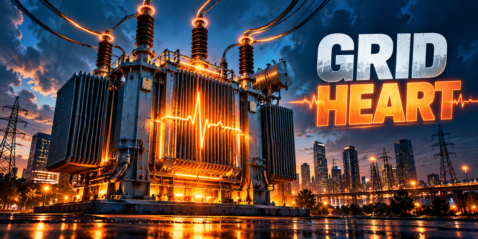
Transformers electric grid operators rely on are among the most important and least visible assets in any power system. They raise voltage so power can travel long distances efficiently, lower it again so it can be used safely, and provide the measurements that protection and control systems depend on. Without transformers in the electric grid, there would be no practical way to link generators, transmission lines and customers that operate at very different voltages.
Their importance is also a source of risk. Many electric grid transformers are costly, built to order and slow to replace, and a single failure can interrupt supply to thousands of customers or reduce the capacity of a substation. As demand grows and new loads such as electric vehicle charging and electrified heating appear, planners and asset managers need to understand both what these machines do and how they age.
This article is written for electrical engineers, grid planners, asset managers, infrastructure leaders and researchers. It explains how grid transformers work, where they fit in the supply chain, the main types and components, how loading and capacity planning work, the common failure modes, and how condition monitoring and lifecycle management support reliability. Equipment classifications and practices vary between utilities and designs, so the examples here are general rather than prescriptive.
What Are Transformers in the Electric Grid?
A transformer is a static electrical device that transfers AC electrical energy from one circuit to another through electromagnetic induction, usually changing the voltage level in the process. It has no moving parts in its main electrical function, which is one reason well-built units can remain in service for decades.
In power systems, the term covers a wide family of equipment. At one end are very large power transformers that connect generation and transmission networks. At the other are small distribution transformers on poles or pads that supply homes and businesses. A separate group, instrument transformers, does not transfer significant power at all. Instead it scales high voltages and currents down to safe levels for meters, relays and control systems.
Together, these devices make it possible to operate a power system at several voltage levels, each chosen for a different purpose. The sections below explain the principle and the roles in more detail.
How Do Grid Transformers Work?
A basic transformer has two or more windings placed around a common magnetic core. When alternating current flows in the primary winding, it creates a changing magnetic flux in the core. That changing flux induces a voltage in the secondary winding. Because the flux must change continuously to induce voltage, transformers operate on AC, not steady DC.
For an ideal transformer, the voltage ratio is approximately equal to the ratio of the number of turns in the windings. More turns on the secondary than on the primary gives a higher secondary voltage (step-up), and fewer turns gives a lower voltage (step-down). Real transformers differ from the ideal because of losses and leakage, but the turns ratio and design determine the voltage transformation.
Power is approximately conserved across an efficient transformer. If voltage is raised, current falls in proportion, and if voltage is lowered, current rises. This is the reason transformers matter so much for transmission. For a given amount of power, a higher transmission voltage means a lower current, and resistive losses in conductors depend on the square of the current. Higher voltage therefore tends to reduce resistive losses, although the actual effect depends on system conditions, conductor design and line length.
Real transformers have two main loss components. Core losses arise in the magnetic core and are present whenever the unit is energized. Winding (load) losses arise from current flowing through the windings and rise with loading. Both produce heat, which is why cooling and temperature management are central to transformer design and operation.
Other design characteristics matter for grid use. The percentage impedance of a transformer influences voltage regulation and the level of fault current it will pass. Ratings, cooling arrangements, voltage levels, winding connections and loading limits all affect how a unit is selected and where it can be applied.
Why Transformers Matter for Grid Reliability and Capacity
Transformers influence the grid in several ways at once.
- Enabling efficient bulk transfer. Step-up transformers allow power to move over long distances at high voltage with lower current.
- Making power usable. Step-down transformers reduce voltage to levels suitable for local distribution and customer equipment.
- Setting capacity limits. The rating of a transformer, together with its cooling and condition, can limit how much power a substation or feeder can deliver.
- Supporting voltage control. Tap changers adjust the turns ratio to help keep voltage within acceptable limits as loading changes.
- Supporting protection and measurement. Instrument transformers feed relays and meters, so protection systems depend on them.
- Influencing reliability. A transformer outage can remove supply or reduce redundancy, particularly where there is no spare capacity or alternative route.
Because replacement can take a long time and involve significant cost, transformers are often treated as critical assets in utility infrastructure. Reliability planning therefore covers both the transformer itself and the options available if it is lost, such as alternative supply, spares or load transfer. For wider context on what drives outages, see the technical, environmental, operational and infrastructure causes of power grid failures.
Main Types of Electric Grid Transformers
Classifications overlap, and terminology differs between utilities and standards. A single transformer can be described in several ways, for example as a power transformer, a substation transformer and a step-down transformer at once.
Power Transformers
Power transformers are generally larger units used in generation and transmission, and in the higher-voltage parts of substations. They are usually designed to operate near their rated load for much of their service and to handle high voltages and large power flows. They are often oil-immersed, with dedicated cooling systems, bushings, tap changers and monitoring devices.
Distribution Transformers
Distribution transformers reduce medium voltage to the lower voltages used by customers. Typical low-voltage supplies vary by region, with 120/240 V and 230/400 V being common examples. They are installed on poles, on pads, in vaults or in enclosures, are produced in large quantities, and generally serve far fewer customers per unit than power transformers. Because there are so many of them, utilities usually manage them as populations rather than as individual assets.
Step-Up and Step-Down Transformers
These terms describe function rather than construction. A step-up transformer raises voltage, such as at a power plant connecting to the transmission network. A step-down transformer lowers voltage, such as at a substation feeding distribution lines or at a pole serving customers. The same transformer design may be used in either direction depending on how it is connected, although in practice units are specified for a particular duty.
Substation Transformers
“Substation transformer” usually refers to the transformers that step voltage down within a substation, for example from a transmission or sub-transmission level to a distribution level. Many are power transformers by construction. Their loading, cooling and condition often determine the firm capacity of the substation, so they are central to capacity planning.
Autotransformers
An autotransformer uses a single winding with a connection partway along it, shared between the primary and secondary circuits, instead of two electrically separate windings. For moderate voltage ratios, this can make the unit smaller and lighter than a two-winding transformer of the same rating. The trade-off is that primary and secondary are electrically connected, with no galvanic isolation, which affects protection, grounding and fault considerations. Autotransformers are common between high-voltage levels in transmission systems.
Instrument Transformers
Instrument transformers scale system quantities down so they can be measured and used safely by meters, protective relays and control equipment.
- Current transformers (CTs) produce a secondary current proportional to the primary current.
- Voltage or potential transformers (VTs or PTs) produce a secondary voltage proportional to the primary voltage. At higher voltages, capacitor voltage transformers are also widely used.
Their accuracy and reliability matter because protection and metering decisions depend on the signals they provide. They also carry specific hazards if secondary circuits are mishandled, so work on them belongs to qualified personnel following approved procedures.
Comparison of Main Transformer Categories
| Type | Typical Role | Typical Location | Purpose |
|---|---|---|---|
| Power transformer | Transfers large amounts of power between voltage levels | Generating stations, transmission and sub-transmission substations | Raise or lower voltage for bulk transfer and network interconnection |
| Distribution transformer | Supplies customers at utilization voltage | Poles, pads, vaults and enclosures on distribution networks | Final voltage reduction for homes, businesses and many industrial users |
| Instrument transformer (CT, VT/PT) | Scales current or voltage for measurement and protection | Substations and switchgear, and at metering points | Provide safe, proportional signals to meters, relays and control systems |
Where Transformers Fit in the Electricity Supply Chain
Transformers appear at nearly every stage between generation and the customer. For the full path, see how power moves through generation, transmission and distribution networks.
Generation
Generators typically produce power at a moderate voltage. Generator step-up transformers raise it to transmission level so it can be exported efficiently. Renewable plants use similar arrangements, with collector systems and step-up transformers connecting wind or solar sites to the network.
Transmission
On transmission systems, power transformers and autotransformers interconnect networks of different voltage levels, and some units control voltage or power flow. Reliability here is especially important because of the large amounts of power involved.
Substations
Substations are where voltage is stepped down, circuits are switched and protection operates. Substation transformers work alongside breakers, switchgear and instrument transformers, and many substations now add more digital monitoring. See digital substations for how that is changing.
Distribution Networks
Medium-voltage feeders leave distribution substations and supply many distribution transformers. These reduce voltage for local circuits and customers. For a comparison of the two network levels, see transmission vs distribution networks.
Commercial, Industrial and Residential Supply
Residential customers are generally supplied through shared distribution transformers. Larger commercial and industrial customers may take supply at medium voltage and use their own transformers on site. Critical facilities such as hospitals and data centers often have additional redundancy, because transformer failure could interrupt operations.
Main Transformer Components and Their Functions
Core and Windings
The core, typically laminated electrical steel, provides a low-reluctance path for magnetic flux. The windings, usually copper or aluminum conductors, carry the current. Their arrangement determines the ratio, impedance and withstand against short-circuit forces.
Insulation System
Insulation separates windings from each other and from the core and tank. In oil-filled units it combines solid insulation, often cellulose-based paper and pressboard, with insulating oil. Insulation condition largely governs how long a transformer can remain in service, because it degrades with heat, moisture, oxygen and electrical stress.
Transformer Oil and Cooling System, Where Applicable
In oil-immersed transformers, oil serves as both insulation and coolant. Heat from the core and windings is carried by the oil to radiators or other heat exchangers, and may be assisted by fans or pumps. Cooling arrangements are commonly described by designations that reflect how oil and air are circulated. Dry-type transformers use air or solid insulation instead of oil, and are often chosen for indoor applications where fire safety is a priority.
Bushings
Bushings carry conductors through the tank wall while keeping them insulated from it. They sit at the point where high voltage meets the tank, so their condition is important to overall reliability.
Tap Changers
Tap changers adjust the turns ratio, and therefore the output voltage. Off-circuit tap changers are adjusted with the transformer de-energized. On-load tap changers operate while the transformer is energized and are widely used for voltage regulation. Because they contain moving mechanical parts and make and break current, they typically need regular attention.
Protection and Monitoring Equipment
Protection and monitoring equipment can include temperature indicators, pressure relief devices, gas-accumulation relays, differential protection and online monitors. These help detect abnormal conditions and can isolate a transformer quickly, but they cannot prevent every failure, and they need correct settings and maintenance to perform as intended.
Transformer Capacity, Loading and Grid Planning
Capacity planning for electric grid transformers starts with ratings and extends to how the unit is actually used. Key considerations include:
- Nameplate rating and cooling stages. Ratings are specified for defined conditions, and many units have higher ratings when additional cooling is in operation.
- Loading profile. Daily and seasonal patterns matter, because temperature depends on the history of loading and ambient conditions, not only on the peak value.
- Temporary overloading. Loading guides from standards bodies describe how short-term loading above rating affects temperature and insulation aging, and any decision to exceed rating should follow the manufacturer’s guidance and a qualified engineering assessment.
- Redundancy and contingency. Many networks are planned so that the loss of one transformer can be covered by others, which sets the firm capacity of a substation.
- Load growth. Electric vehicle charging, electrified heating, new industrial loads and distributed generation can change both peak demand and load shape.
- Impedance and fault levels. These affect voltage regulation, parallel operation and the fault current that downstream equipment must withstand.
- Losses and lifecycle cost. Purchase price is only part of the cost, since core and winding losses accumulate over many years.
- Spares and lead times. Strategies for spare units, standardization and procurement lead times can influence how quickly service can be restored.
Planning is rarely a matter of one number. The same transformer might be acceptable under normal conditions and become a constraint when a neighboring unit is out of service, or when ambient temperatures are high.
Common Transformer Failure Modes
Transformers can fail for many reasons, and failures often result from several interacting factors. The list below describes typical failure modes, not a ranking by frequency, and no failure rates are implied.
Insulation Degradation
Solid and liquid insulation age gradually under thermal, electrical and chemical stress. Moisture, oxygen, contaminants and sustained high temperature can accelerate aging. Weakened insulation is less able to withstand electrical stress from switching or lightning surges, which can lead to breakdown.
Winding Faults
Winding faults include turn-to-turn or winding-to-ground failures and mechanical deformation. Through-fault currents can create large forces on windings, and cumulative effects may loosen or displace them, reducing their ability to withstand subsequent events.
Overheating and Overloading
Sustained high loading, poor cooling or high ambient temperature raise winding and oil temperatures, increasing insulation aging. Hot spots can also produce gases in the oil. The effect depends on the duration and magnitude of the overload as well as the design.
Bushing Failures
Bushings can fail because of insulation deterioration, moisture ingress, contamination, mechanical damage or electrical stress. Because of where they sit, a bushing failure can damage the transformer and nearby equipment.
Oil Leaks and Oil-Quality Deterioration
Leaks may result from gasket aging, corrosion or mechanical damage and can allow moisture entry or reduce oil level. Oil quality can decline through moisture, oxidation, contamination and dissolved by-products, reducing its insulating and cooling performance.
Cooling-System Problems
Fan, pump, radiator or control problems reduce heat removal. The effect may not be noticeable until loading or ambient temperature increases, which is why cooling performance is worth checking independently of general condition.
Tap-Changer Problems
Mechanical wear, contact deterioration, contamination of tap-changer oil and control issues can all affect on-load tap changers. These problems may show up as abnormal operation, changes in monitored quantities or maintenance findings.
External Faults and Environmental Stresses
Short circuits on connected networks, lightning and switching surges, flooding, wildfire, contamination, extreme temperatures, vegetation, animals and vandalism can all stress transformers. Environment affects both the likelihood of events and the condition of the equipment over time.
Transformer Condition Monitoring and Diagnostics
Condition monitoring combines periodic tests, inspections and, where installed, online monitoring to assess condition. Common methods include:
- Dissolved gas analysis (DGA) of oil samples, which looks at gases that may be produced by certain thermal or electrical stresses.
- Oil quality tests such as moisture content, acidity and dielectric properties.
- Temperature and loading records for oil, winding (measured or estimated) and ambient conditions.
- Thermographic inspection of external connections, bushings and radiators.
- Electrical diagnostic tests such as insulation resistance, power factor or dissipation factor, winding resistance, turns ratio and frequency response analysis.
- Partial discharge monitoring where applicable, using electrical, acoustic or other methods.
- Tap-changer and cooling-system checks, which can include operation counts, motor current and status.
An important distinction is between a warning sign and a confirmed fault. A high temperature reading might reflect heavy loading, high ambient temperature, a sensor problem or an actual cooling failure. A gas result may indicate developing stress or may be affected by past events, oil treatment or sampling practice. Indicators must be interpreted using manufacturer guidance, applicable standards, operating history and qualified engineering assessment, and trends are generally more informative than single values. Offline tests usually require specific isolation and safety procedures carried out by qualified personnel.
For a deeper look at how monitoring data feeds decisions, see sensors, IoT devices and intelligent monitoring in grid operations.
Transformer Maintenance and Asset Management
Maintenance and asset management aim to keep transformers safe and available for as long as is technically and economically sensible. Common elements are:
- Routine inspection: checking oil levels, leaks, cooling equipment, bushings, gauges and the general condition of the site.
- Periodic testing and sampling: following a schedule set by the utility, manufacturer guidance and applicable standards.
- Planned maintenance: work on tap changers, cooling systems, gaskets, bushings and protection devices, carried out by qualified personnel under approved procedures, with appropriate isolation and safety controls.
- Defect management: recording, prioritizing and tracking issues until they are resolved.
- Records: keeping nameplate data, test results, loading history and events in a form that can be analyzed.
- Lifecycle decisions: deciding between continued operation, refurbishment, reduced loading or replacement.
Maintenance approaches range from time-based schedules to condition-based and predictive methods. Condition-based and predictive maintenance require suitable data, diagnostic interpretation and engineering judgment, and they do not remove the need for baseline inspections. Increasingly, utilities also weigh condition against criticality, meaning the consequences of failure, so that attention goes first to units where a problem would matter most.
How Transformers Support Grid Modernization and Renewable Energy Integration
Modernization changes what is asked of transformers. A smart grid adds sensing, communications and analytics to the physical network, and transformers are both a beneficiary and a data source in that picture.
- Renewable connection. Step-up transformers connect wind and solar plants, and the variable output of these resources can change loading patterns compared with conventional generation.
- Two-way flows. Rooftop solar and storage can send power back through distribution transformers, which were traditionally designed with one-way flow in mind.
- Harmonics and cycling. Power electronics, such as inverters and some loads, can introduce harmonic currents and more variable loading, which may affect heating and design requirements.
- New demand. Charging and electrified heating can increase local transformer loading and change when peaks occur.
- Better visibility. Metering and sensing can provide information about loading and voltage conditions. See advanced metering infrastructure (AMI) and why grid modernization depends on real-time visibility.
How much these effects matter depends on the network, the level of distributed generation and the design of each transformer.
Digital Monitoring, AI and Predictive Maintenance
Sensors and software can improve the information available about transformers. Online monitors for temperature, gases, moisture, bushings and loading can supply frequent data, and analytics can look for trends or unusual behavior. Machine learning is sometimes used for anomaly detection and for estimating failure risk where enough reliable historical data exists. For broader context, see artificial intelligence in smart grids.
It is important to be realistic about what these tools do. They can help engineers notice changes sooner and prioritize inspections, but they cannot guarantee that failures will be prevented. Limitations include:
- Sensor drift, gaps and incorrect asset records can distort results.
- Major failures are rare, which makes models hard to train and validate.
- An alert may reflect normal operating conditions rather than a fault, and false alarms can lead to alert fatigue.
- Models need explainability, validation and monitoring over time, and results need review by qualified engineers.
Used as decision support within a sound maintenance program, digital monitoring is valuable. Used as a substitute for engineering judgment, it can mislead.
Practical Illustrative Scenarios
The scenarios below are illustrative examples written to explain engineering reasoning. They are not real-world case studies, and the details are hypothetical.
Scenario 1: Distribution Transformer Serving a Growing Residential Area
- Context: a pole-mounted or pad-mounted transformer supplies a neighborhood where new homes, electric vehicle chargers and heat pumps are being added.
- Potential concern: loading may rise over time, particularly during evening peaks, leading to higher temperatures and faster insulation aging, or to voltage problems for customers at the end of the circuit.
- Engineering response: review loading estimates and available interval data from metering where it exists, compare with the transformer rating, and consider load balancing, upgrading the unit or adding capacity as part of the area plan.
- Limitations: load data may be incomplete at the transformer level, customer connections may be uncertain, and adoption of new loads is hard to predict. Planning should allow for uncertainty.
Scenario 2: Substation Transformer With Increased Loading During Peak Demand
- Context: a substation transformer experiences higher peaks during hot weather, with a second transformer at the same substation providing contingency capacity.
- Potential concern: if one unit is out of service during a peak, the remaining unit may be loaded above its rating, which raises temperature and affects insulation life. Reduced cooling or high ambient temperature compounds the effect.
- Engineering response: assess loading against rating using loading guides and manufacturer data, check that cooling equipment is working, review load-transfer options, and consider whether upgrades or additional capacity are needed.
- Limitations: the calculations depend on accurate load, temperature and design data, and any decision to operate above rating needs qualified engineering assessment of the specific unit.
Scenario 3: Transformer Showing Abnormal Temperature or Oil-Related Indicators
- Context: a power transformer shows a gradual rise in oil temperature relative to load, and a recent oil test shows a change in dissolved gas results.
- Potential concern: these are warning signs that may reflect reduced cooling, developing insulation stress or another internal issue. They are not by themselves confirmation of a fault.
- Engineering response: verify the data first by checking sensors and sampling practice, then review trends against loading and history, compare against standards and manufacturer guidance, increase sampling frequency, inspect cooling equipment and arrange further diagnostic tests under approved safety procedures.
- Limitations: indicators can have more than one explanation, and a past event or maintenance activity can change readings. Diagnosis may remain uncertain until further evidence is gathered.
Scenario 4: Transformer Requiring Refurbishment or Replacement
- Context: an older transformer at a critical substation has a history of defects and mixed test results. Replacement would take a long time to arrange.
- Potential concern: continued operation may carry a rising likelihood of failure, and the consequences of loss are significant because of the load served and limited backup.
- Engineering response: combine condition evidence, criticality and lifecycle cost to compare options such as continued operation with closer monitoring, refurbishment, reduced loading, and replacement. Begin procurement planning early where replacement is a realistic option, and arrange contingency measures such as spares or load transfer.
- Limitations: remaining life cannot be predicted precisely, internal condition is hard to observe directly, and cost and outage constraints may limit the choices.
Transformer Reliability: Key Metrics and Considerations
Metrics help show whether transformers are being operated and maintained as planned. The table gives examples. Definitions and thresholds should be set by each organization, based on manufacturer guidance, standards and its own experience, and no universal thresholds are implied.
| Metric | What It Measures | Why It Matters | Interpretation Notes |
|---|---|---|---|
| Loading relative to rating | Actual load compared with the unit’s rated capacity, including peaks and duration | Loading drives temperature, aging and available capacity | Consider cooling stage, ambient conditions and contingency scenarios, not only peak values |
| Temperature trends | Oil and winding temperature over time, relative to load and ambient | Changes can signal cooling or internal issues | Compare with the unit’s own baseline; check sensor health before drawing conclusions |
| Inspection completion | Share of scheduled inspections and tests completed on time | Shows whether the evidence for condition assessment is current | Distinguish critical units from routine ones, and record valid deferrals |
| Oil-test trends | Changes in results such as dissolved gases and moisture over successive samples | Trends may show developing stress or oil deterioration | Interpret with guidance, history and sampling consistency; a single result is rarely conclusive |
| Unresolved defects | Open defects or recommendations, and how long they have been outstanding | Shows whether identified issues are being addressed | Classify by severity so serious items are not hidden among minor ones |
| Unplanned outages | Unexpected outages of transformers, including cause where known | An outcome measure of reliability | Many factors influence it, so it should not be attributed to maintenance alone |
| Maintenance history | Completeness and quality of records of work, findings and repairs | Good records support diagnosis and lifecycle decisions | Consistent coding and linking to the correct asset are essential |
Challenges Facing Modern Electric Grid Transformers
- Aging fleets. Many networks include transformers that have been in service for a long time, and age combined with loading history can affect condition.
- Rising and changing demand. New loads and generation can alter loading and power flow patterns.
- Long lead times and supply constraints. Large units are often custom designed, so replacement can be slow and costly.
- Extreme weather and environment. Heat, storms, flooding and wildfire can stress equipment and sites.
- Data quality. Incomplete records and inconsistent test data limit diagnostics and analytics.
- Limited outage windows. Maintenance and testing often need transformers to be taken out of service, which is difficult where there is little redundancy.
- Skills and knowledge. Transformer engineering and diagnostics need experienced people, and knowledge can be lost as staff retire.
- Environmental and safety considerations. Oil containment, fire protection and end-of-life handling need to be managed.
- Cybersecurity. As monitoring and communication systems expand, the connected devices around transformers need protection.
Best Practices for Utility Transformer Planning and Management
- Keep an accurate asset register with ratings, design details, locations and history for every transformer.
- Plan capacity for contingencies, not only for normal conditions, and review plans as load and generation change.
- Follow manufacturer guidance and applicable standards for loading, testing and maintenance.
- Combine condition and criticality when prioritizing inspection, maintenance and investment.
- Use trends, not single readings, and verify unusual data before acting on it.
- Keep qualified people and approved procedures at the center of work, with proper isolation, grounding and safety controls. Never bypass or defeat protection to keep a unit in service.
- Manage defects to closure and record findings in a structured way.
- Plan spares and replacement early, given long lead times, and consider standardization where it makes sense.
- Evaluate lifecycle cost, including losses, maintenance and risk, not only purchase price.
- Introduce monitoring and analytics deliberately, starting with critical units and validating results against engineering judgment.
- Review outcomes and feed lessons from failures and inspections back into planning.
Future Trends in Transformer Technology
Several developments are under way or expected, although timing and adoption vary by utility and none is guaranteed to deliver particular results:
- More built-in sensing and monitoring, making condition data available more frequently.
- Alternative insulating fluids, such as natural and synthetic esters, used for fire safety and environmental reasons in some applications.
- Efficiency improvements, through better core materials and design, driven by lifecycle loss considerations and regulation in some regions.
- Solid-state and power-electronics-based transformers, which are still emerging for most grid applications and offer possible control features.
- Improved analytics and digital twins, to support planning and scenario analysis, subject to data quality and validation.
- Greater focus on resilience and spares, including approaches to speed up restoration after major failures.
For a broader outlook, see the electric grid in 2035.
Key Takeaways
- Transformers in the electric grid transfer AC energy by electromagnetic induction, and the turns ratio and design set the voltage transformation.
- Raising voltage for transmission lowers current for a given power, which can reduce resistive losses depending on system conditions.
- Power, distribution and instrument transformers have different roles, and classifications vary by utility and design.
- Rating, cooling, impedance, loading and contingency planning all matter for capacity and reliability.
- Failure modes include insulation degradation, winding faults, overheating, bushing, oil, cooling and tap-changer problems, and external stresses.
- Warning signs are not confirmed faults, and need interpretation using guidance, standards, history and qualified engineers.
- Protection, sensors and predictive maintenance help, but cannot prevent every failure.
- Good records, criticality-aware prioritization and early replacement planning support lifecycle management.
Conclusion
Transformers connect the different voltage levels of the power system, set capacity limits at substations and feeders, and supply the signals that protection and metering rely on. Their condition and loading therefore influence reliability across the whole supply chain.
Managing electric grid transformers well means understanding how they work, planning capacity with contingencies in mind, interpreting condition evidence carefully and making lifecycle decisions that consider both condition and consequence. New loads, renewable generation and digital monitoring are changing the context, but the fundamentals remain the same: sound data, appropriate standards, qualified people and safe procedures.
Frequently Asked Questions About Transformers in the Electric Grid
What role do transformers play in the electric grid?
Transformers change voltage levels so electricity can be transmitted efficiently and delivered safely. Step-up units raise voltage for transmission, step-down units lower it for distribution and customers, and instrument transformers supply scaled signals to meters and protection systems.
They also influence capacity and reliability, because their ratings and condition limit how much power can be delivered.
How do electric grid transformers work?
Alternating current in the primary winding creates a changing magnetic flux in the core, which induces a voltage in the secondary winding. The ratio of turns largely determines the voltage change, and power is approximately conserved, so higher voltage means lower current.
Because they rely on changing flux, transformers operate on AC and produce some losses as heat that must be managed through design and cooling.
Why are transformers important for the electric grid?
They allow power to move efficiently at high voltage, then be reduced to usable levels, and they support voltage control and protection. Their capacity and condition can limit substations and feeders, and failures can be costly and slow to repair.
Good planning, monitoring and maintenance help manage these risks but cannot remove them entirely.
What are the main components of grid transformers?
The main components are the core and windings, the insulation system, oil and cooling equipment where applicable, bushings, tap changers, and protection and monitoring devices. Each has a specific function and can affect reliability.
Not all transformers include every component; dry-type and small distribution units, for example, are simpler.
What challenges affect transformers in the electric grid?
Challenges include aging equipment, changing and growing demand, long replacement lead times, extreme weather, limited outage windows, data quality, skills shortages and cybersecurity of connected monitoring. Failure modes such as insulation degradation, overheating and tap-changer or bushing problems also need active management.
Managing these challenges depends on planning, condition assessment and qualified engineering judgment.
Where are electric grid transformers used?
They are used at power plants, along transmission networks, in substations, on distribution feeders, and at commercial, industrial and residential supply points. Instrument transformers are used in substations, switchgear and metering installations.
The exact types and ratings depend on the voltage level, the function and the utility’s practices.

I share real stories, practical ideas and honest perspectives on business, marketing and life. This blog is a space to learn, grow and connect.