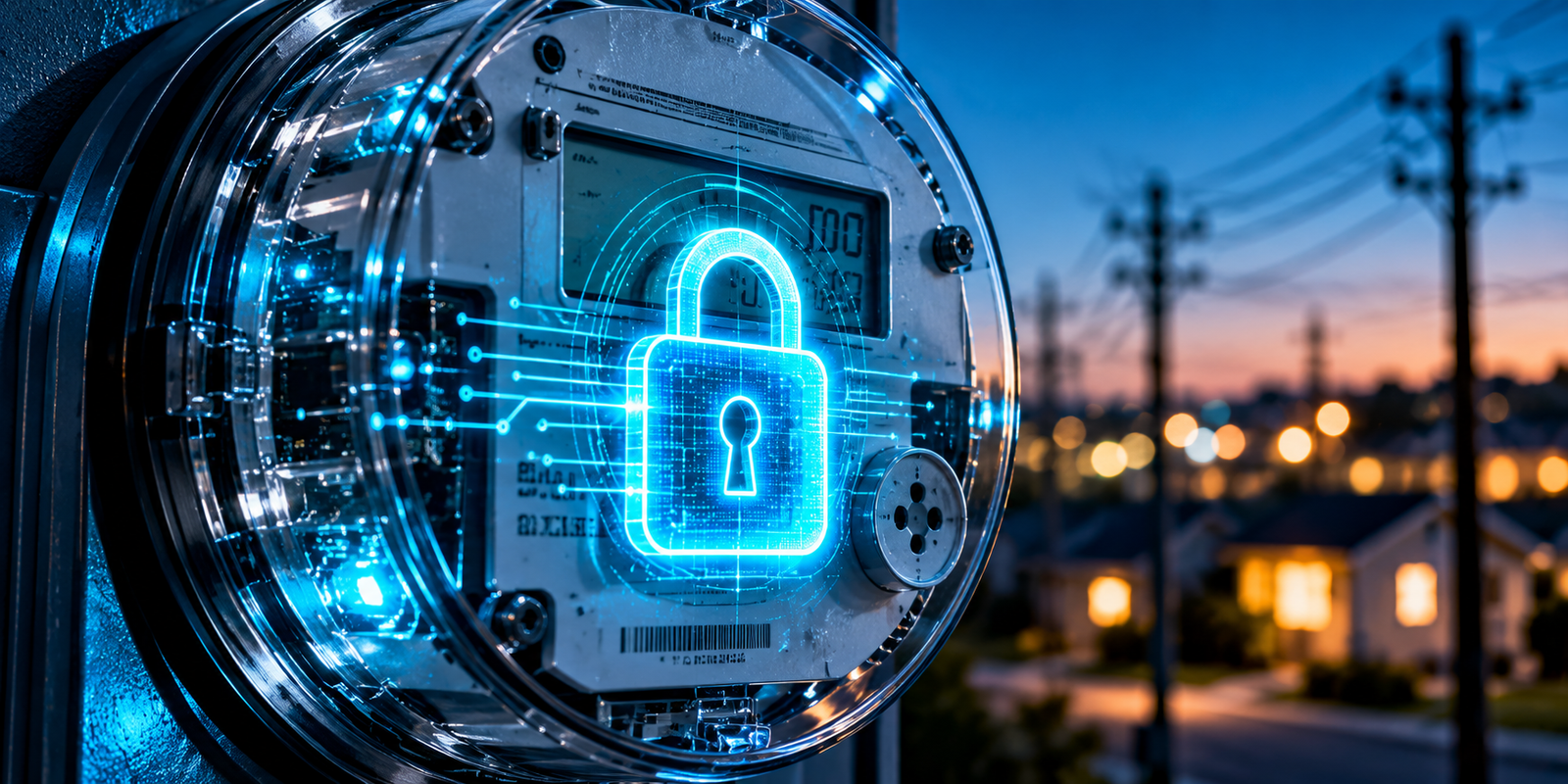

Advanced metering infrastructure (AMI) is the complete system that measures electricity use at customer premises, communicates that data to the utility and manages it for billing, operations and planning. A smart meter is only the field device at one end of that system. AMI also includes the communication network, the head-end system (HES), the meter data management system (MDMS) and the utility applications that use the data.
That is the key difference between a smart meter and AMI. A smart meter records consumption and events. AMI is the connected infrastructure that moves those records to utility systems, lets the utility send commands back where supported, validates the data and delivers it to billing, outage, planning and customer applications. Traditional meter reading collected a number occasionally. AMI turns metering into a continuous data infrastructure.
Utilities deploy AMI to reduce manual reading, obtain more frequent data, improve outage awareness, support time-based tariffs and demand response, and give planners better visibility of load. Architectures differ between utilities, so this article describes common patterns rather than a single design. For wider context, read what is a smart grid.
- AMI is a complete metering and communication ecosystem, not a single device.
- Smart meters collect electricity-related measurements and events.
- Communication networks move meter information to utility systems.
- The head-end system (HES) manages communication with meters.
- The meter data management system (MDMS) validates, stores and manages meter data.
- Utility applications use AMI data for operations, planning and customer services.
- AMI creates an important data foundation for modern utility systems.
What Is Advanced Metering Infrastructure?
Advanced metering infrastructure is an integrated system of smart meters, communication networks, data management systems and utility applications that collects, transfers and manages electricity usage and meter event data.
Several related terms are often mixed up:
- Smart meter: the field device that measures consumption and records events.
- Smart metering: the practice or process of using such meters.
- Automated meter reading (AMR): automatic collection of readings, often one-way, without the full two-way system.
- AMI: the broader system, which generally provides two-way communication.
| Technology | Main Capability | Communication | Typical Data Flow |
|---|---|---|---|
| Smart meter | Measures usage and events | Built-in communication module, varies by model | Meter to network |
| Smart metering | Using smart meters for readings and services | Depends on deployment | Meter to utility, varies |
| AMR | Automated reading collection | Often one-way, such as drive-by or fixed network | Meter to reader or collector |
| AMI | Complete system for collection, management and applications | Generally two-way | Meter to HES to MDMS to applications, and commands back |
Architectures vary, so these descriptions are general rather than universal.
Why Utilities Use AMI
Utilities deploy AMI for operational and customer reasons:
- Automated meter reading and reduced manual meter-reading activity
- More frequent meter data and remote communication with meters
- Outage-related awareness
- Voltage information, remote configuration and similar functions where supported
- Customer usage visibility and demand analysis
- Billing support
- Distribution planning and load forecasting
- Demand response
- Operational analytics
Some capabilities are generally possible with AMI, such as interval readings and remote reading. Others depend on the specific architecture, meter model and utility configuration, such as voltage data, remote disconnection or in-home data access. A utility should define which functions it needs before selecting equipment.
AMI Architecture
A common conceptual flow is:
Customer premises
Where electricity is consumed.
Smart meter
Measures and records data.
Neighborhood or access communication network
Connects meters locally.
Data concentrator or gateway, where applicable
Aggregates traffic from many meters.
Backhaul network
Carries aggregated data to the utility.
Head-end system (HES)
Manages communication with meters.
Meter data management system (MDMS)
Validates and manages data.
Utility applications
Use the processed data.
Billing, CIS, analytics and operations
Business and operational processes.
Each layer has a defined job. The meter measures, the access network collects locally, backhaul carries data over distance, the HES handles meter communication, the MDMS handles data quality and storage, and applications turn data into decisions.
AMI architectures vary. Some deployments use data concentrators, while others connect meters directly to a cellular network. Some use RF mesh, others use power line communication or a mix. No single structure applies to every deployment. For how AMI sits within a broader system, see key smart grid components.
Smart Meters
The smart meter is the field device in an AMI system. It sits at the customer connection and performs several functions:
- Energy measurement of electricity consumed, and exported where applicable.
- Time-based measurements in intervals where configured.
- Voltage and current-related measurements where supported.
- Power-quality-related information where supported.
- Tamper and event information.
- Outage and restoration events.
- Meter status and diagnostics.
- Communication functions, including sending data and receiving commands.
- Remote functions where supported, such as configuration updates.
Exact capabilities depend on the meter model, configuration and the utility’s deployment.
| Smart Meter Capability | Example Utility Use |
|---|---|
| Interval energy measurement | Billing, load analysis, time-based tariffs |
| Register readings | Billing and verification |
| Voltage measurement (where supported) | Voltage analysis along feeders |
| Power-quality information (where supported) | Investigating supply issues |
| Tamper and event detection | Revenue protection, field investigation |
| Outage and restoration events | Outage awareness and verification |
| Remote configuration (where supported) | Updating settings without a site visit |
| Two-way communication | Commands, on-demand reads, program support |
AMI Communication Networks
The communication layer connects meters to the head-end. Options include RF mesh, cellular, power line communication (PLC), fiber, Ethernet, private utility networks and, in some cases, other wireless or satellite links. The general technologies are compared in smart grid communication networks. Here the focus is AMI.
Two parts of the network matter:
- Access network: connects meters to a collection point, such as an RF mesh, PLC or direct cellular link.
- Backhaul network: carries aggregated traffic from collection points to the utility, often using fiber, cellular or other wide-area links.
AMI-specific design factors include:
- Coverage: reaching every meter, including basements and rural sites.
- Reliability and availability: consistent delivery over time.
- Latency: usually less critical for billing data than for control.
- Bandwidth and scalability: supporting very large meter counts and interval data.
- Device density: many meters in one area can congest a network.
- Remote-area challenges: sparse locations may need different technology.
No single technology fits every service territory, so many utilities combine more than one.
Head-End System (HES)
The head-end system (HES) is the software that communicates with smart meters through the AMI network, collecting data and sending commands.
The HES typically handles communication management, meter connectivity, data collection, command handling, meter events, device status, communication monitoring and data transfer to downstream systems. The path is:
Meter
Sends readings and events.
Communication network
Carries the messages.
HES
Receives, organizes and forwards them.
The HES is an important interface between field meters and utility applications. It hides the details of meter communication so that downstream systems can work with consistent data. Feature sets differ between products and deployments, so the HES in one utility may not match another.
Meter Data Management System (MDMS)
A meter data management system (MDMS) is the platform that ingests, validates, stores and manages meter data and delivers it to utility applications.
An MDMS generally covers data ingestion, validation, estimation, editing where required, storage, aggregation, data organization, meter data access, data quality management and data delivery to downstream applications.
Its key quality process is VEE: Validation, Estimation and Editing:
- Validation: checking that data is complete, plausible and consistent.
- Estimation: filling gaps using approved methods when data is missing.
- Editing: correcting records where appropriate, with audit records.
VEE matters because billing, analytics and planning rely on trustworthy data. The flow is:
Raw meter data
Arrives from the HES.
Validation
Checks completeness and plausibility.
Estimation, if needed
Fills gaps by approved rules.
Editing, where appropriate
Corrects with traceability.
Validated meter data
Ready for use.
Utility applications
Consume the data.
VEE rules differ between utilities and regulators, so they are not prescribed here.
AMI Data Flow
The end-to-end flow for meter data is:
The smart meter measures electricity
Consumption is recorded in intervals or registers.
The meter stores or records the data
Data and events are held until transmitted.
The communication network transfers it
Via access and backhaul networks.
The HES receives or collects the data
Reads may be scheduled or on demand.
The HES passes data to the MDMS
Through defined interfaces.
The MDMS validates and manages it
VEE and storage take place.
Utility applications consume the data
Billing, outage and analytics systems access it.
Billing, analytics or operations use it
Business and operational processes act.
Where two-way communication is supported, the reverse direction runs:
Utility system
Initiates a request or command.
HES
Formats and sends it.
Communication network
Carries it to the meter.
Smart meter
Executes it and responds.
Exact workflows vary by architecture, and not every meter supports every command.
AMI Data Types
AMI produces several categories of data. Not every meter provides every type.
| Data Type | What It Represents | Potential Utility Use |
|---|---|---|
| Interval energy data | Consumption in set time intervals | Billing, load profiles, forecasting |
| Register readings | Cumulative energy totals | Billing, verification |
| Meter events | Status changes and alarms | Field investigation, diagnostics |
| Outage events | Loss of supply at the meter | Outage awareness |
| Restoration events | Return of supply | Restoration verification |
| Voltage-related measurements (where supported) | Supply voltage at the meter | Voltage analysis |
| Power-quality information (where supported) | Disturbances or variations | Supply quality investigation |
| Tamper events | Signs of interference | Revenue protection |
| Communication status | Whether the meter is reachable | Network monitoring |
| Device status | Health and configuration | Asset and lifecycle management |
AMI and Billing
AMI supports billing through meter readings, interval data, time-of-use structures, remote data collection, data validation and billing integration. Remote collection reduces dependence on manual meter reading, and interval data allows tariffs that vary by time of day.
AMI does not automatically eliminate billing errors. Errors can still arise from meter configuration, customer-account data, rate setup or integration faults. The MDMS and VEE processes help catch issues before data reaches billing.
AMI for Outage Management
AMI can contribute to outage awareness through outage and restoration events and meter communication status. Analysts can also look for outage patterns across many meters. The path is:
Meter event
The meter records loss of supply, where supported.
HES
Receives the event.
MDMS or utility system
Passes it onward.
Outage management workflow
Operators and systems interpret it.
AMI can provide additional visibility, but it does not replace all outage-management technologies. During an outage, meters may lose power and communication, and a network failure can resemble a customer outage, so utilities combine AMI with SCADA, fault indicators, customer calls and other sources.
AMI and Customer Energy Visibility
AMI can support customer-facing information such as consumption history, interval usage, usage patterns, time-based consumption, energy awareness, customer portals where implemented and demand-response programs. Customers can see when they use energy, not just how much.
Customer data needs careful handling. Not every deployment provides real-time customer dashboards, and many present data with a delay after collection and validation. What customers see depends on the utility’s systems and policies.
AMI and Demand Response
AMI data can support demand-response programs through load profiles, consumption patterns, program measurement, event analysis, customer participation tracking and load-shifting analysis. After an event, the utility can compare interval data against expected usage to estimate the response.
AMI is often an enabling data infrastructure for demand response, not a demand-response program by itself. Programs also need rules, customer enrollment, signaling methods and sometimes controllable devices.
AMI and Grid Operations
AMI data can contribute to distribution operations: load analysis, voltage visibility where available, outage awareness, feeder-level analysis, distribution planning, asset planning, loss analysis and demand forecasting. Aggregated meter data helps planners see how load behaves on a transformer or feeder.
AMI data and SCADA data are not interchangeable:
- AMI data: customer-edge data, often collected in intervals and delivered with some delay.
- SCADA data: real-time operational data from substations and feeder equipment, used for supervision and control.
They complement each other. See real-time grid data for how timing affects use.
AMI and the Smart Grid
AMI is one important component of the broader smart-grid ecosystem:
Smart grid
The overall system.
Grid modernization
The wider upgrade effort, which includes:
AMI, SCADA, DMS and EMS
Metering and control systems.
Distribution automation and IoT
Field automation and connected devices.
Digital substations
Digital protection and control.
Analytics and AI
Interpretation of data.
AMI contributes the customer-edge data layer. For the wider picture, read how smart grid technology works, IoT in smart grids and artificial intelligence in smart grids.
AMI Integration With Utility Systems
AMI delivers value only when it connects to other systems:
- CIS and billing systems for customer accounts and invoices.
- MDMS for validated meter data.
- OMS and DMS for outage and distribution operations.
- Data warehouses and analytics platforms for analysis.
- Customer portals and demand-response platforms for customer services.
Integration is challenging because of:
- APIs and interfaces that differ between systems.
- Data formats that need translation.
- Data synchronization across systems with different timing.
- Legacy systems with limited interfaces.
- Data ownership questions between departments.
Clear data models and interface standards reduce this effort. For the broader context of integration difficulty, see smart grid deployment challenges.
AMI Data Quality Challenges
Common issues include missing readings, duplicate readings, communication gaps, incorrect timestamps, meter configuration problems, invalid values, data gaps, estimation requirements and inconsistent data formats. VEE processes exist to catch and manage these problems.
| Data Quality Issue | Possible Impact | Typical Mitigation |
|---|---|---|
| Missing readings | Incomplete usage records | Retry collection, estimation by approved rules |
| Duplicate readings | Double counting in analysis | De-duplication on ingestion |
| Communication gaps | Delayed or absent data | Network monitoring, redundancy, gap filling |
| Incorrect timestamps | Misaligned intervals | Time synchronization, validation checks |
| Meter configuration errors | Wrong scaling or intervals | Configuration audits, commissioning checks |
| Invalid values | Implausible readings affect billing or analysis | Range and consistency validation |
| Inconsistent formats | Integration failures | Standard data models and interface testing |
AMI Communication and Reliability Challenges
AMI networks face practical reliability issues: limited coverage, high device density, weak signal quality, remote locations, communication failures, latency, network congestion, power outages and device availability. Meters in basements or dense buildings may be hard to reach, and storms can disrupt backhaul and cell sites.
Utilities design for resilience with:
- Coverage surveys and field testing before large rollouts
- Redundant paths and backup power at collection points
- Meters that store data and send it when communication returns
- Network monitoring that finds failing devices early
- Mixed technologies where one network does not fit all areas
No single communication technology is universally best, and the right choice depends on terrain, density, cost and service requirements.
AMI Cybersecurity
AMI creates a very large population of connected field devices, so security is a core design requirement. Defensive measures include:
- Device authentication and access control.
- Secure communication and encryption.
- Key and certificate management where applicable.
- Network segmentation between AMI and other systems.
- Secure firmware and patch management.
- Monitoring and logging of devices and system activity.
- Incident response planning.
- Vendor security requirements across the supply chain.
Because meters stay in the field for many years, update processes and key lifecycle management need planning from the beginning.
AMI Privacy and Data Governance
Meter data can reveal patterns of household activity, so it needs responsible governance. Key elements include:
- Protecting customer consumption data with access control.
- Data minimization: collecting and keeping only what is needed.
- Retention rules that define how long data is kept.
- Data sharing rules for third parties and programs.
- Governance and auditability: clear ownership and records of access.
Requirements vary by location and regulatory environment. This article does not provide legal advice, and utilities should follow the rules that apply to them.
AMI Deployment Challenges
Successful AMI deployment requires more than installing smart meters. Challenges include large-scale meter replacement, communication infrastructure, legacy integration, data migration, system integration, cybersecurity, workforce training, customer communication, device lifecycle, vendor management, cost, maintenance and data quality. The wider set of issues is discussed in smart grid deployment challenges.
Field installation, back-office integration and customer communication all need to work together, and a gap in any of them can delay benefits.
Traditional Metering vs AMI
Traditional metering remains useful. Electromechanical and basic electronic meters are simple, long-lived and adequate where only periodic consumption totals are needed. The comparison below is general.
| Aspect | Traditional Metering | AMI |
|---|---|---|
| Meter reading | Manual or periodic | Automated, remote |
| Communication | None or one-way | Generally two-way |
| Data frequency | Periodic totals | Interval data, event data |
| Remote access | Limited | Remote reads and commands where supported |
| Outage awareness | Mostly customer reports | Meter events can add visibility |
| Customer visibility | Limited, periodic | Usage history and patterns |
| Data management | Simple records | HES, MDMS and VEE processes |
| Billing support | Reading-based billing | Interval-based, time-based billing options |
| Demand response | Limited measurement | Data to support programs |
| Grid analytics | Limited | Load and planning analysis |
| Maintenance | Periodic field visits | Device and network monitoring, with system upkeep |
| Scalability | Labor grows with meter count | Scales with network and system capacity |
AMI adds capability but also adds systems, security responsibility and cost. For the wider comparison, see smart grid vs traditional grid.
AMI Use Cases
Some use cases depend on the specific AMI deployment, as marked.
| AMI Use Case | Data Used | Utility Benefit |
|---|---|---|
| Automated meter reading | Register or interval readings | Less manual reading effort |
| Billing support | Validated interval and register data | Data-based billing, time-based tariffs |
| Outage awareness | Outage and restoration events (where supported) | Additional visibility of supply loss |
| Load analysis | Interval data | Better understanding of demand patterns |
| Demand forecasting | Historical interval data | Improved planning inputs |
| Demand response | Load profiles, event data | Program measurement |
| Voltage analysis (where supported) | Voltage measurements | Insight into supply voltage at customers |
| Customer energy visibility | Consumption history | Customer awareness of usage |
| Distribution planning | Aggregated load data | Better transformer and feeder planning |
| Loss analysis | Meter and network data | Support for identifying loss patterns |
| Asset planning | Loading and usage trends | Prioritizing equipment attention |
| Operational analytics | Events, communication status | Monitoring of the AMI system and network |
Illustrative AMI Data Flow Example
Illustrative Example — not a real utility case study.
A utility wants to analyze electricity usage for a group of customers.
Smart meters record interval consumption
Usage is stored in regular intervals.
Data moves through the AMI communication network
Access and backhaul networks carry it.
The HES collects the information
It also records which meters did not respond.
The MDMS receives and validates the data
Checks flag missing or implausible values.
VEE processes incomplete or questionable records
Estimation and editing follow approved rules.
Validated data becomes available to applications
Analytics tools can access it.
Analysts review consumption patterns
They look at peaks and time-of-day behavior.
The utility uses the information
For planning or customer programs.
No outcomes or figures are implied. The example shows how data moves and where quality checks fit.
How Utilities Can Plan an AMI Deployment
AMI should be treated as a long-term utility platform rather than a meter replacement project. A practical roadmap:
- Define business and operational objectives.
- Assess existing metering infrastructure.
- Define data requirements such as interval length and event types.
- Select meter capabilities that match those needs.
- Select communication architecture suited to the territory.
- Design HES and MDMS architecture.
- Plan integration with utility systems.
- Define cybersecurity requirements.
- Establish data governance and VEE processes.
- Pilot the solution in a limited area.
- Validate field performance against objectives.
- Train staff in operations, field work and data use.
- Scale deployment in phases.
- Monitor lifecycle performance and plan upgrades.
Future of AMI
This outlook describes possibilities, and future systems will not all have identical capabilities. Current AMI already supports interval data, events and remote communication. Emerging directions include:
- More granular meter data where networks and storage allow.
- Improved communication and edge processing in meters or gateways.
- Advanced analytics and AI/ML applied to meter data.
- Better outage visibility.
- DER integration and EV load visibility.
- Advanced demand response and more intelligent distribution planning.
- Improved customer energy insights.
- Greater integration with smart-grid platforms.
See future smart grid technology for the wider outlook.
Conclusion
Advanced metering infrastructure is a complete connected metering ecosystem, and smart meters are only one part of it. Communication networks connect meters to utility systems, the HES manages meter communication and collection, and the MDMS validates and manages meter data. Utility applications then turn that data into operational and customer value.
AMI supports billing, outage awareness, planning, demand response and analytics, but data quality and cybersecurity are foundational. Successful AMI requires technology, integration, people and governance working together. To continue, explore how smart grid technology works and smart grid components.
Frequently Asked Questions About Advanced Metering Infrastructure
What is advanced metering infrastructure?
Advanced metering infrastructure (AMI) is an integrated system of smart meters, communication networks, a head-end system, a meter data management system and utility applications. It collects electricity usage and meter event data and makes it available for billing, operations and planning.
Unlike a smart meter alone, AMI includes the full path from the meter to utility systems.
How does advanced metering infrastructure work?
Smart meters record consumption and events and send them over a communication network, sometimes through a gateway or data concentrator. The head-end system collects the data and passes it to the meter data management system, which validates and stores it.
Utility applications such as billing and analytics then use the data. Where two-way communication is supported, commands can travel back from the utility to the meter.
Why is advanced metering infrastructure important?
AMI gives utilities frequent, remotely collected meter data instead of occasional manual readings. This supports billing, outage awareness, load analysis, demand response and planning.
It also forms a data foundation for broader smart grid applications. The benefits depend on system design, data quality, security and integration.
What are the main components of advanced metering infrastructure?
The main components are smart meters, communication networks, the head-end system (HES) and the meter data management system (MDMS). Utility applications such as billing, CIS, outage management and analytics use the processed data.
Some deployments also include data concentrators or gateways. Cybersecurity and data governance support all components.
What are the challenges of advanced metering infrastructure?
Common challenges include large-scale meter replacement, communication coverage and reliability, integration with legacy systems and data quality. Cybersecurity, privacy, cost, workforce training and device lifecycle management also matter.
Utilities address them with pilots, careful architecture, VEE processes, security controls and phased deployment.
Where is advanced metering infrastructure used?
AMI is used by electric utilities for residential, commercial and industrial customers. Applications include billing, outage awareness, load analysis, demand forecasting, demand response and customer energy information.
Deployment extent and capabilities vary by utility, region and regulation.
What is the difference between AMI and a smart meter?
A smart meter is the field device that measures electricity use and records events. AMI is the whole system around it, including the communication network, HES, MDMS and utility applications.
A smart meter without that supporting infrastructure cannot deliver the data management and applications that AMI provides.
What is the difference between HES and MDMS?
The head-end system (HES) manages communication with meters, collecting data, handling commands and monitoring device connectivity. The meter data management system (MDMS) receives that data, validates it, estimates or edits it where needed, stores it and delivers it to applications.
In short, the HES talks to the meters, and the MDMS manages the data. Their exact features vary by product and utility.

I share real stories, practical ideas and honest perspectives on business, marketing and life. This blog is a space to learn, grow and connect.