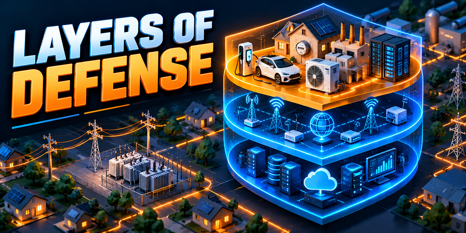

Smart grid communication is the set of wired and wireless networks that moves measurements, status, alarms and control commands between grid devices and utility systems. So what is smart grid communication in practice? It is the information layer that lets a smart meter, a sensor, a relay or a battery system report what is happening and receive instructions, while the electricity itself travels separately over lines, cables and transformers.
That distinction matters. Electricity flow is physical: power moves from generation through transmission and distribution to customers. Information flow is digital: data moves between field devices, gateways, communication networks and control platforms. A modern utility needs both, and the second depends entirely on the quality of the communication network that carries it.
Smart meters, grid sensors, intelligent electronic devices (IEDs), remote terminal units (RTUs), SCADA, advanced metering infrastructure (AMI), distribution management systems (DMS), energy management systems (EMS), IoT devices and automation schemes all rely on communication. A sensor that cannot report is a local instrument. A control center that cannot reach a switch has visibility without action. Utilities therefore treat communication as core infrastructure, and no single technology fits every application. Fiber, RF mesh, cellular, private radio and other options each suit different distances, speeds, reliability needs and budgets.
This article focuses on the communication layer only. For the definition of the smart grid, read what is a smart grid. For old versus new networks, see smart grid vs traditional grid. For a device-by-device reference, see key components of a smart grid, and for the end-to-end workflow, read how smart grid technology works from field devices to utility control systems. Here the question is narrower: how do smart grid devices actually communicate?
Smart grid communication connects field devices, meters, sensors, substations and utility control systems so measurement and control information can move between the physical grid and digital platforms. Different connectivity options, such as RF mesh, cellular, fiber and private utility networks, are selected according to coverage, latency, reliability, bandwidth, cost, security and operational requirements.
What Is Smart Grid Communication?
Smart grid communication is the network of wired and wireless technologies that carries measurement, monitoring, status, control and operational information between grid devices and utility systems.
The central concept is a loop. Field devices create data. A communication network carries it, usually through a gateway or edge device. A utility platform receives and processes it. The result is data for people and applications, or a control command that travels back over the network to a field device.
Communication can occur at several points in that chain:
- Device to gateway: A sensor or meter sends data to a local collection point.
- Device to substation: Field equipment reports to substation systems.
- Substation to control center: RTUs, IEDs and gateways pass data to SCADA and other platforms.
- Meter to utility platform: Smart meters send readings and events to AMI systems.
- DER to utility platform: Solar, storage and other resources report output and status.
- Control center to field equipment: Operators or automation send commands and settings.
Communication is the information layer, not the electricity delivery layer. A cable that carries data does not carry the power the data describes. The physical network is covered in our guide to electricity transmission and distribution.
Why Is Smart Grid Communication Important?
Smart grid communication is what turns isolated devices into a system. The logic is straightforward:
-
No measurement
No useful data exists in the first place.
-
No communication
Data cannot reach the systems that need it.
-
No data
Visibility and control are limited.
Reliable communication supports many utility functions:
- Visibility: Real-time or near-real-time views of grid conditions.
- Smart metering: Interval readings, meter events and two-way messaging.
- Remote monitoring: Equipment and environmental conditions at remote sites.
- Fault detection: Faster location of faulted sections.
- Automation and remote switching: Control actions without a crew visit.
- Asset monitoring: Condition data for transformers, breakers and other equipment.
- DER coordination and renewable integration: Visibility into distributed generation and storage.
- Demand response: Signals that ask flexible loads to adjust.
- Outage management: Meter and device events that help locate and verify outages.
- Grid analytics: Data feeds for forecasting and planning.
Each benefit is conditional. Communication enables these functions, but results depend on device quality, network design, data handling and operating procedures. The wider case for data-driven operation is explored in why grid modernization depends on better electricity data and real-time visibility.
How Does Smart Grid Communication Work?
The workflow has ten steps. In practice, several happen almost simultaneously, and some stay local to a device.
-
A field device measures a condition
Voltage, current, temperature, status or consumption is sensed.
-
The device creates data
The measurement is converted into a digital message.
-
A local controller or gateway collects it
Data from several devices is gathered, formatted or filtered.
-
The communication network transports the data
RF mesh, cellular, fiber, private radio or another path carries it.
-
The utility platform receives it
SCADA, AMI, DMS, EMS or a data platform accepts the message.
-
The data is validated and processed
Timestamps, ranges and quality flags are checked.
-
An operator or application uses the information
Displays, alarms and analytics present it.
-
A control command may be sent back
An operator or configured automation issues an instruction.
-
The field device receives the command
The command travels back over the network and is executed.
-
The device reports the resulting condition
New data confirms whether the action worked.
As a compact flow, the path looks like this:
-
Sensor or meter
Measures and creates data.
-
Gateway or edge device
Collects, translates and filters.
-
Communication network
Transports the data.
-
Utility platform
Receives, validates and stores.
-
Analytics or control
Interprets and decides.
-
Communication network
Carries the command back.
-
Field device
Acts and reports again.
Not every function uses the full loop. Fast protection decisions are made locally inside IEDs, because waiting for a round trip to a control center would be too slow. Communication then reports what happened, and coordinates wider actions.
Smart Grid Communication Architecture
Utilities usually describe smart grid communication networks in layers. Names and boundaries vary by utility and vendor, but the following structure is common.
Field Layer
This layer contains the devices that measure and act:
- Smart meters
- Grid sensors
- Intelligent electronic devices (IEDs)
- Remote terminal units (RTUs)
- Programmable logic controllers (PLCs)
- DER devices such as solar inverters, battery systems and EV chargers
Field and Access Network
The access network connects field devices to a collection point. Options include:
- RF mesh
- Cellular
- Local wireless links
- Wired connections
Backhaul Network
Backhaul aggregates traffic from many access networks and carries it toward the control center. It commonly uses:
- Fiber
- Utility wide-area networks (WANs)
- Microwave links where appropriate
- Cellular backhaul
Control and Utility Network
This layer hosts the operational systems:
- SCADA
- DMS
- EMS
- AMI head-end and meter data systems
- Operational data platforms
Enterprise and Analytics Layer
This layer supports planning and decision-making:
- Data lakes or data platforms
- Analytics and AI/ML
- Asset management systems
- Planning systems
The layers are usually separated by security boundaries and gateways. A smart meter does not normally talk directly to an enterprise analytics tool. Data passes through successive layers, each applying its own validation, protocol translation and access rules.
RF Mesh Communication
RF mesh is a wireless network in which devices communicate by radio and can relay each other’s messages, so data can hop across several devices to reach a collection point.
In a mesh, each device, such as a smart meter or distribution device, acts as both an endpoint and a relay. If one path is blocked, traffic may use another. This multi-hop behavior lets the network extend coverage without a separate base station near every device. Devices typically forward data to a collector, access point or gateway, which links the mesh to the backhaul network.
RF mesh is widely associated with AMI, where large numbers of meters sit relatively close together. It is also used for some distribution monitoring and automation applications where the data rates and response times involved are suitable.
| RF Mesh Feature | Explanation |
|---|---|
| Coverage | Extends through multi-hop relaying; strongest where devices are dense enough to reach each other |
| Scalability | Well suited to large populations of similar devices such as meters |
| Resilience | Alternate paths may be available if a link or device fails |
| Latency | Generally higher than fiber and varies with hop count and network load |
| Bandwidth | Typically moderate to low, suited to meter data and modest control traffic |
| Deployment considerations | Needs planning for collector placement, device density, terrain and radio interference |
Actual performance depends on network design, device density, terrain, vegetation, buildings and interference. Sparse rural areas may need additional relays or a different technology. Dense urban areas may bring interference or signal-blocking challenges. RF mesh is therefore a good fit for certain distributed applications rather than a universal answer.
Cellular Communication
Cellular communication uses mobile network infrastructure to connect devices that may be scattered across a wide area. Utilities may use 4G LTE, 5G and cellular IoT technologies designed for low-power, low-data-rate devices. Connectivity can come from public mobile networks operated by carriers, or from private cellular networks that a utility, or a partner on its behalf, operates for its own use.
Typical utility applications include:
- Remote sensors and monitoring devices
- Distribution devices such as reclosers and capacitor controllers
- DER monitoring for solar, storage and other resources
- Substation communication, often as a backup or secondary path
- Mobile or temporary installations
- Smart meters in some deployments
| Cellular Feature | Explanation |
|---|---|
| Coverage | Wide where carrier networks exist; weaker in remote, underground or shielded locations |
| Latency | Moderate and application-dependent; newer generations are designed to improve it |
| Bandwidth | Moderate to high, depending on technology and network |
| Availability | Depends on carrier infrastructure, congestion and backup power at cell sites |
| Deployment | Often quick, because no utility-built network is needed in the public-network case |
| Network dependency | Public networks depend on the carrier’s coverage, service terms and restoration priorities |
Cellular is attractive where devices are spread out and building a private network would be costly. The trade-off is dependence on infrastructure the utility does not control. Utilities often assess carrier coverage, service-level terms and resilience during storms or emergencies, and some pair cellular with a second path for critical functions.
Fiber Communication
Fiber-optic communication carries data as light through glass strands. It is widely used in high-capacity utility environments because it combines high bandwidth, low latency, long reach and immunity to electromagnetic interference, which is helpful inside high-voltage substations.
Typical utility roles include:
- Substations: Station networks that connect IEDs, gateways and protection schemes.
- Control centers: High-capacity links to major sites and data systems.
- Utility WANs: Backbone connectivity between facilities.
- High-capacity backhaul: Aggregating traffic from access networks such as RF mesh or cellular gateways.
| Fiber Feature | Explanation |
|---|---|
| Bandwidth | High, with room to grow as data demands increase |
| Latency | Low, which helps time-critical applications |
| Distance | Suited to long routes between substations and control centers |
| Reliability | High when designed with redundant routes or ring topologies |
| Interference | Not affected by electromagnetic interference in the same way as copper |
| Installation cost | Can be high, especially for long routes, trenching or reaching individual field devices |
Fiber is rarely used to reach every meter or pole-top device, because the installation cost per endpoint is high. It is more often the backbone behind wireless access networks. Physical routes also need protection from cable cuts, construction damage and weather.
Private Utility Networks
A private utility network is communication infrastructure that a utility owns, controls or dedicates to its own operational use. It can include private wireless, dedicated radio systems, utility WANs and microwave links where appropriate.
Utilities may choose private networks because they offer:
- Operational control: The utility sets design, priorities and maintenance schedules.
- Critical infrastructure support: Important traffic need not share capacity with public users.
- Remote-site reach: Networks can be planned to cover substations, rural feeders and generation sites that public networks serve poorly.
- Coverage by design: Tower placement and radio planning follow the utility’s service territory rather than a carrier’s commercial footprint.
- Greater control over network design: Redundancy, backup power and security policies can match operational needs.
The trade-offs are cost, spectrum access, skilled staff and long-term maintenance. Private networks require planning, licensing or spectrum arrangements where applicable, and equipment lifecycle management. Many utilities therefore run a mix: private networks for critical functions and public or shared networks for less critical ones.
Other Smart Grid Communication Options
Several other technologies appear in utility communication. Suitability depends heavily on the application, and not every option is appropriate for utility control.
- Wi-Fi: Used for local connectivity, such as inside substations, depots and some distribution equipment. Range is limited, and security and interference need careful management.
- Bluetooth and other short-range technologies: Common for local configuration, commissioning and maintenance access to devices, rather than wide-area communication.
- LPWAN technologies: Low-power wide-area networks suit devices that send small amounts of data infrequently, such as some environmental or asset monitoring sensors. They are generally not intended for low-latency control.
- Microwave: Point-to-point radio links that can connect sites where laying fiber is impractical, with capacity that is often substantial but dependent on line of sight and weather conditions.
- Satellite: Useful for very remote locations without terrestrial coverage. Latency is typically higher, so it is better suited to monitoring and non-time-critical functions.
- Wired Ethernet: Standard in substations, control rooms and data centers, often running over copper or fiber within a facility.
- Power line communication (PLC): Sends data over power conductors. It can reach devices without a separate communication cable, but performance depends on line conditions, noise and network topology. In this article, PLC means power line communication, not programmable logic controllers.
The right question is not which technology is best, but which one meets the requirements of a specific function at an acceptable cost and risk.
Communication Technology Comparison
The table below summarizes common smart grid communication technologies in qualitative terms. It deliberately avoids precise performance figures, because real results depend on equipment, design, spectrum and local conditions.
| Technology | Typical Use | Coverage | Latency | Bandwidth | Key Strength | Main Consideration |
|---|---|---|---|---|---|---|
| RF mesh | AMI, some distribution devices | Local to regional, density-dependent | Moderate, varies with hops | Low to moderate | Self-extending, scalable for many devices | Terrain, density and interference affect performance |
| Cellular | Scattered field devices, DERs, remote monitoring | Wide, where carrier coverage exists | Application-dependent | Moderate to high | Broad reach and quick deployment | Dependence on carrier networks and resilience |
| Fiber | Substations, control centers, backbone | Along installed routes | Low | High | Capacity, low latency, reliability | Installation cost and route protection |
| Private wireless | Critical field communication, remote sites | Designed to the service area | Low to moderate | Moderate to high | Utility control over design and priorities | Spectrum, cost and operating skills |
| Microwave | Point-to-point links, backhaul | Line-of-sight links | Low to moderate | Moderate to high | Connects sites where fiber is impractical | Line of sight, weather and tower maintenance |
| Satellite | Very remote assets | Wide, including remote areas | Higher, application-dependent | Low to moderate | Reaches places without terrestrial networks | Delay and recurring service cost |
| Power line communication | Metering and some local devices | Follows the power network | Application-dependent | Low to moderate | Uses existing conductors | Line noise and topology effects |
| Ethernet | Substation and facility networks | Local | Low | High | Standardized and widely supported | Limited to a site; needs segmentation and security design |
For quick extraction, each row follows one pattern: technology, use, strength, limitation, application. No row implies that a technology is mandatory or always suitable.
Smart Grid Communication for AMI
AMI relies on communication to carry data from meters to utility applications. The usual path is:
-
Smart meter
Records usage and events.
-
RF mesh, cellular or power line communication
Carries the data from the meter.
-
Collector or gateway
Aggregates traffic and connects to backhaul.
-
Head-end system
Manages communication with meters.
-
Meter data management
Validates, stores and prepares readings.
-
Utility applications
Billing, outage tools, analytics and customer systems.
It helps to separate three things that are often confused:
- Smart meter: The field device that measures consumption and records events.
- AMI communication network: The RF mesh, cellular, power line or other network that carries meter data.
- AMI software platform: The head-end and data management systems that control meters and process data.
Communication supports automated meter reading, two-way communication, meter event reporting, outage information, load data, demand response signals and customer information. Two-way communication matters because AMI is more than automated reading: the utility can also send commands or settings to meters where the system supports it. Read about the broader device set in key components of a smart grid.
Communication for Grid Sensors
Grid sensors measure conditions, but a measurement has operational value only when it reaches a system that can interpret it. The communication path is usually:
-
Sensor
Measures a condition.
-
Local device
Collects, converts or filters the signal.
-
Communication
Carries the data to the utility.
-
Monitoring platform
Stores, displays and analyzes it.
Sensors may report voltage, current, temperature, power quality, equipment condition, fault indicator status and environmental conditions. Their communication needs differ widely. A fault indicator may send a small event message that must arrive promptly. A temperature sensor may report periodically. A power-quality monitor may generate larger data volumes. Matching the network to the data pattern avoids both under- and over-engineering.
Our article on how sensors, IoT devices and intelligent monitoring are changing electrical grid operations covers the devices in depth. This article covers the networks behind them.
Communication for SCADA
SCADA depends on communication between field equipment and the control center. The basic path is:
-
Field device
Breaker, transformer or other equipment.
-
RTU or IED
Collects status and measurements.
-
Communication network
Carries data to the control center.
-
SCADA
Stores, alarms and displays it.
-
Operator
Interprets and decides.
Communication carries several kinds of information: equipment status, analog measurements, alarms and events, and control commands going the other way. Typical connections include RTU to SCADA, IED to a substation system, and substation to control center. Utilities use established utility protocols for these exchanges, and the choice depends on equipment age and design.
SCADA is also found in conventional utilities. What changes in a smart grid is the reach and integration of communication around it, not the existence of SCADA itself. Control commands deserve extra care, because an incorrect or delayed command can have physical consequences. Utilities therefore apply authentication, command confirmation and operating procedures to control paths.
Communication for Distribution Automation
Distribution automation uses communication to monitor and operate equipment along feeders. It supports:
- Automated switches and reclosers
- Fault indicators
- Fault location, isolation and service restoration (FLISR)
- Remote switching
- Voltage control
- Distribution management through DMS
Requirements depend on the scheme. A remote switch operated by an operator after review can tolerate more delay than an automated scheme in which devices coordinate within seconds. Some schemes use peer-to-peer messaging between field devices, while others rely on a central system. Whichever approach is used, the network must meet the response-time and reliability needs of the specific application, including during storms and outages, when reliable communication matters most.
Communication is also a design constraint on automation. If a link is unreliable, the utility may limit what is automated, add redundancy, or keep operators in the loop. For wider context, see our guide to power system automation.
Communication for Digital Substations
Substations use some of the most demanding communication in the grid. In digital substations, IEDs exchange information over Ethernet-based networks, commonly using the IEC 61850 standard. At a high level:
- Station bus: Connects IEDs, gateways and station-level systems for status, measurements and control.
- Process bus: Links field-side equipment, such as merging units, with protection and control devices where designed that way.
- GOOSE: Fast event messaging between devices, used for functions such as interlocking and protection signaling.
- Sampled Values: Streams of digitized current and voltage measurements.
- Station-level communication: Connects substation systems to gateways and onward to the control center.
Not every digital substation uses the same architecture. Some use a station bus only, some add a process bus, and designs differ in redundancy, time synchronization and segmentation. Communication requirements therefore vary with the design and application. For details, read digital substations: architecture, automation, communications and operational benefits.
Communication for DERs and Renewable Energy
Distributed energy resources (DERs) include rooftop solar, utility-scale solar, wind, battery storage, microgrids and other distributed generation. Communication gives utilities visibility into these resources and, where arrangements allow, a way to coordinate them.
Typical information includes:
- Monitoring and status: Whether the resource is online, curtailed or in an alarm state.
- Power output: Real-time generation or export levels.
- Forecasting support: Output history and local conditions that improve forecasts.
- Control signals: Setpoints, limits or schedules where programs or interconnection rules permit.
- State of charge: For batteries and storage-enabled systems.
- Coordination: Aggregated management of many small resources.
Different resources use different paths. Rooftop systems often connect through the customer’s internet service, an inverter vendor’s cloud, or a utility-managed link. Utility-scale plants usually have dedicated communication with SCADA. Microgrid controllers coordinate local resources and may exchange data with the utility.
Communication helps utilities coordinate distributed resources, but it does not by itself solve renewable integration. Network capacity, protection design, market rules, forecasting and planning all still matter.
Communication for Electric Vehicles
EV charging adds load that can be large and clustered. Communication links chargers, charging networks and utility or aggregator platforms. It supports:
- Smart charging: Scheduling or limiting charging based on signals.
- Load monitoring: Visibility into charger and feeder loading.
- Demand response: Programs that shift or reduce charging at peak times.
- Charging coordination: Spreading demand across time or locations.
- Vehicle-to-grid: An emerging capability in which vehicles may export energy, currently limited to pilots and specific programs.
Where supported, communication allows charging behavior to be coordinated with grid conditions. Support depends on the charger, the vehicle, the charging network and the utility program, so it should not be assumed everywhere.
Communication for Energy Storage
Battery systems depend on continuous information exchange. The flow is:
-
Battery
Produces operating data.
-
Monitoring
Battery and power-conversion systems track conditions.
-
Communication
Carries data and commands.
-
Energy management system or utility platform
Schedules and dispatches.
-
Control
Charge and discharge commands reach the system.
Communication carries state of charge, power output, charging and discharging status, alarms, temperature and availability. Reliable communication allows storage to be coordinated with solar output, feeder conditions and market or operating needs. It also supports safety, because operating limits and alarms must reach operators promptly. Storage controllers typically include local protection that functions even if communication is lost.
Latency, Reliability and Availability
These terms are often used loosely, but each describes a different property of a communication network.
Latency
Latency is how long information takes to travel from sender to receiver. Protection signaling needs very low latency, while monthly meter readings tolerate much more.
Reliability
Reliability is how consistently information is delivered correctly. A network can be fast but lose messages under load.
Availability
Availability is how often the communication service is operational. Redundant paths and backup power typically improve it.
Bandwidth
Bandwidth is how much data the network can carry. Streaming waveform data needs more than periodic voltage readings.
Coverage
Coverage is where the network can reach, including rural, urban, indoor and underground locations.
| Requirement | Why It Matters in Smart Grids |
|---|---|
| Latency | Time-critical functions such as protection and automation need messages delivered within tight limits |
| Reliability | Lost or corrupted messages can leave operators with incomplete or misleading information |
| Availability | Control and monitoring must work during storms and outages, when they are most needed |
| Bandwidth | Higher data volumes from sensors, meters and DERs require adequate capacity |
| Coverage | Devices in rural, indoor or underground sites must be reachable |
| Scalability | Networks must handle growing numbers of devices without redesign |
| Security | Communication paths carry operational data and control commands that must be protected |
These requirements trade off against each other and against cost. A function that needs high availability may justify redundant fiber and backup power, while a monthly reading may be well served by a simpler network.
How Utilities Choose a Smart Grid Communication Technology
There is no universally best technology. Utilities typically weigh the following factors for each application:
- Application criticality: What happens if communication fails?
- Required response time: How quickly must data or commands arrive?
- Coverage: Can the network reach every device location?
- Reliability: How consistently must messages be delivered?
- Availability: How much downtime is acceptable?
- Bandwidth: How much data will flow now and later?
- Security: Can authentication, encryption and monitoring be supported?
- Interoperability: Does it work with existing equipment and standards?
- Existing infrastructure: Can current fiber, towers or radio be reused?
- Installation cost: What is the upfront investment?
- Operating cost: What recurring fees and maintenance apply?
- Environmental conditions: Heat, flooding, terrain and weather exposure.
- Scalability: Can the network grow with device counts?
- Maintenance: Who supports and updates it, and for how long?
- Regulatory requirements: What rules apply to spectrum, data and reliability?
In practice, most utilities build a hybrid network, combining fiber for the backbone, wireless access networks for field devices, and cellular or satellite where other options are impractical.
Communication Networks for Different Grid Applications
The matrix below shows options that may suit each application. It is illustrative, not prescriptive, because choices depend on local conditions and utility policy.
| Application | Suitable Communication Options | Main Requirement |
|---|---|---|
| Smart meters | May include RF mesh, cellular or power line communication | Scalability and consistent delivery across many endpoints |
| Distribution sensors | Can include RF mesh, cellular or LPWAN | Coverage and low power use at scattered locations |
| Substations | May include fiber, Ethernet and microwave | Low latency, high reliability and redundancy |
| SCADA | Can include fiber, private wireless, microwave and cellular as a secondary path | Availability and secure control paths |
| Distribution automation | May include private wireless, RF mesh, cellular or fiber | Response time suited to the automation scheme |
| DERs | Can include cellular, internet-based links, fiber and private wireless | Visibility, secure integration and standard interfaces |
| Battery storage | May include fiber, Ethernet, cellular and private wireless | Reliable monitoring and dispatch |
| EV charging | Can include cellular, internet-based links and Ethernet | Coordinated control and load visibility |
| Control centers | May include fiber and utility WAN connections | High capacity and redundant routes |
| Remote rural assets | Can include cellular, satellite, microwave and private radio | Coverage in areas with limited infrastructure |
Smart Grid Communication and Cybersecurity
Communication networks are critical infrastructure. They carry operational data and control commands, so a weakness in the network can affect visibility, reliability and safety. Utilities therefore apply defensive cybersecurity across communication design, with practices that include:
- Authentication: Verifying devices, users and systems before they connect.
- Encryption where appropriate: Protecting data in transit, taking into account latency and device capability.
- Access control: Limiting who and what can reach which systems.
- Network segmentation: Separating operational networks from business and public networks.
- Secure device management: Maintaining inventories, credentials and configurations.
- Monitoring: Watching network behavior for unusual activity.
- Secure updates: Applying tested firmware and software updates through controlled processes.
- Incident response: Having rehearsed procedures for detection, containment and recovery.
- Backup and recovery: Keeping tested copies of configurations and data.
- Operational technology (OT) security: Accounting for long-lived field equipment with constraints different from office IT.
Security is a lifecycle activity rather than a one-time feature. Utilities generally follow recognized industry frameworks and regulatory requirements that apply in their region, and design security in from the start of a communication project rather than adding it afterward.
Smart Grid Communication and Data Quality
Communication affects data quality as well as data delivery. A failing or congested network can produce:
- Missing data: Messages that never arrive.
- Delayed data: Messages that arrive too late to be useful.
- Duplicate data: Repeated messages after retries.
- Incorrect status interpretation: A stale value shown as current, or a lost message read as a change in equipment state.
Utilities manage these risks through several practices:
- Timestamping: Recording when a measurement was taken, not only when it arrived.
- Synchronization: Keeping device clocks aligned so events can be ordered correctly.
- Data validation: Flagging implausible or out-of-range values.
- Communication monitoring: Tracking link health, message loss and device connectivity.
- Error detection: Using checks that identify corrupted messages.
- Data quality checks: Marking data as good, suspect or missing so analytics and operators can treat it appropriately.
More data does not automatically mean better decisions. Data that arrives late or without quality indicators can mislead operators and analytics alike.
Challenges of Smart Grid Communication
| Challenge | Why It Matters | General Response |
|---|---|---|
| Rural coverage | Sparse areas may lack suitable networks | Combine technologies; consider private radio or satellite |
| Underground environments | Signals may not penetrate vaults or basements | Use repeaters, antennas or wired links |
| Interference | Radio noise can degrade performance | Plan frequency use; survey sites |
| Legacy equipment | Older devices may lack modern interfaces | Use gateways, retrofit or replace by priority |
| Interoperability | Mixed vendors and protocols complicate integration | Adopt open standards and test integrations |
| Cybersecurity | More connected devices increase the need for protection | Layered, defensive security and monitoring |
| Network reliability | Control and monitoring depend on dependable links | Redundant paths and backup power |
| Installation cost | Networks require significant upfront investment | Phase deployments; reuse existing assets |
| Maintenance | Radios, fiber and devices need upkeep | Inventories, monitoring and managed updates |
| Data volume | Large data streams strain networks and storage | Edge filtering and scalable platforms |
| Device density | Many devices in one area can congest networks | Capacity planning and traffic management |
| Vendor dependency | Proprietary systems can limit flexibility | Prefer standards-based, multi-vendor designs |
| Workforce skills | Teams need power, network and security expertise | Training and cross-disciplinary teams |
| Extreme weather | Storms, heat and floods can damage networks when they are needed most | Hardened equipment, backup power and diverse routes |
Smart Grid Communication vs Traditional Utility Communication
Traditional utilities already used communication. SCADA, radio, telephone circuits, fiber and other systems have long supported substations and control centers. The difference in smart grid communication is generally the breadth, integration, connectivity and digital capabilities, not the presence of communication itself. For the wider architectural comparison, see smart grid vs traditional grid.
| Area | Traditional Utility Communication | Modern Smart Grid Communication |
|---|---|---|
| Device connectivity | Focused on major sites and equipment | Extends to feeders, meters, DERs and customer-side devices |
| Data frequency | Often periodic or limited to key points | More frequent, with interval and event-based data |
| Coverage | Concentrated on substations and transmission | Broader across distribution and the grid edge |
| Monitoring | Limited visibility on distribution feeders | Wider monitoring of equipment and conditions |
| Remote control | Available at selected sites | Extended to more field devices where justified |
| Metering | Manual or periodic reading, one-way in many cases | AMI with two-way communication |
| Automation | Limited, often local | Remote and coordinated automation functions |
| Analytics | Periodic studies on limited data | More continuous analytics on richer data |
| DER integration | Limited visibility of distributed resources | Monitoring and coordination options |
| Communication architecture | Often separate, siloed systems | More integrated, layered and managed networks |
Illustrative Example: Communication Across a Smart Distribution Network
Illustrative example — not a real utility case study.
Consider a fictional distribution feeder with smart meters, grid sensors, automated switches, rooftop solar, battery storage and EV chargers. In the early evening, solar output falls while EV charging rises. The following sequence shows how communication carries information through the system.
-
Sensors collect measurements
Voltage and current sensors report a downward voltage trend.
-
Smart meters collect customer data
Meter data shows rising demand as solar export declines.
-
RF mesh or cellular carries field information
Access networks move data from scattered devices to gateways.
-
Fiber provides backhaul where applicable
Higher-capacity links carry aggregated traffic toward the control center.
-
The DMS receives the data
Operators see an updated view of the feeder.
-
Analytics identify changing conditions
The trend suggests voltage may approach its lower limit.
-
An operator reviews the situation
The operator confirms the cause and available options.
-
Automation responds where configured
Voltage equipment adjusts, and storage or charging may be coordinated within set limits.
-
Field devices report the result
New readings travel back over the network and show whether voltage recovered.
The example shows why one technology rarely does everything. Each step uses the network that fits the device, the distance and the response time required.
Future of Smart Grid Communication
This is an informed outlook, not a guarantee, and developments will differ by utility and region.
- More connected devices: The number of connected grid devices is expected to keep growing as sensors, DERs and chargers spread.
- Private 5G where appropriate: Some utilities are exploring private 5G for field and campus applications, though deployment depends on spectrum, cost and use case.
- Improved edge computing: More processing may happen close to devices, reducing data sent upstream and enabling faster local responses.
- More distributed intelligence: Devices could coordinate locally, reducing reliance on a central system for some functions.
- Better network management: Tools for monitoring, configuring and troubleshooting large device networks are likely to improve.
- Advanced AMI: Meters may take on more grid-edge sensing and communication roles.
- More DER connectivity: Standard interfaces for distributed resources are emerging and may ease integration.
- Improved interoperability: Standards work could reduce vendor lock-in and integration effort.
- AI-assisted network monitoring: Analytics may help detect communication faults and anomalies earlier, with human oversight.
- Greater cybersecurity requirements: As connectivity grows, security expectations and regulation are expected to grow with it.
For the broader outlook, see the future electric grid and grid digitalization.
Conclusion
Smart grid communication is the information layer that connects field devices, meters, sensors, substations and utility control systems. It does not deliver electricity, but without it the grid cannot be seen, analyzed or controlled in the way modern operations require.
RF mesh is useful for distributed applications such as AMI. Cellular provides broad wireless connectivity for scattered devices. Fiber supports high-capacity and critical backhaul. Private networks give utilities control over design and priorities, and other technologies such as microwave, satellite, Ethernet, LPWAN and power line communication serve specialized needs. The right choice depends on operational requirements, and reliability, latency, security and coverage matter most.
Done well, smart grid communication enables smart metering, monitoring, automation and DER coordination across a hybrid, layered network. To continue the topic, explore how smart grid technology works, power system automation and grid modernization and real-time visibility.
Frequently Asked Questions About Smart Grid Communication
What is smart grid communication?
Smart grid communication is the network of wired and wireless technologies that carries measurement, status, control and operational information between grid devices and utility systems. It connects smart meters, sensors, IEDs, RTUs and substations with platforms such as SCADA, AMI, DMS and EMS. It is the information layer, not the electricity delivery layer.
How does smart grid communication work?
A field device measures a condition and creates data, and a gateway or local controller collects it. A communication network such as RF mesh, cellular or fiber carries the data to a utility platform, where it is validated and used by operators or applications. A control command may then travel back over the network to a field device, which reports the result.
Why is smart grid communication important?
Without communication, grid devices can measure conditions but cannot share the data with the systems that need it. Communication supports visibility, smart metering, fault detection, automation, DER coordination and outage management. Its value depends on the reliability, latency and security of the network.
What are the main components of smart grid communication?
The main components are field devices such as meters, sensors, IEDs and RTUs, plus access networks like RF mesh and cellular. Gateways and edge devices connect them to backhaul networks such as fiber or microwave. Utility platforms including SCADA, AMI, DMS and EMS receive the data, and cybersecurity controls protect the whole path.
What are the challenges of smart grid communication?
Key challenges include coverage in rural and underground locations, interference, legacy equipment, interoperability and cybersecurity. Installation cost, maintenance, data volume, device density and extreme weather also matter. Utilities usually respond with hybrid networks, redundancy, open standards and phased deployment.
Where is smart grid communication used?
It is used across substations, distribution feeders, customer meters, control centers and distributed energy resources. Applications include AMI, SCADA, distribution automation, digital substations, DER monitoring, battery storage and EV charging. The technologies used vary by utility, region and application.
What is the difference between RF mesh and cellular communication?
RF mesh is a utility-deployed wireless network in which devices relay each other’s messages toward a collector, which suits dense groups of devices such as meters. Cellular uses mobile network infrastructure to connect devices directly over a wide area, often with quicker deployment. RF mesh gives the utility more control over the network, while cellular depends on carrier coverage and service.
Why is fiber communication important for smart grids?
Fiber offers high bandwidth, low latency, long reach and immunity to electromagnetic interference. These qualities suit substations, control centers, utility WANs and backhaul that aggregates traffic from wireless access networks. It is usually less practical for reaching every individual field device because of installation cost.

I share real stories, practical ideas and honest perspectives on business, marketing and life. This blog is a space to learn, grow and connect.